AluTeam BR 248-2 Скачать руководство пользователя страница 5

Series 248-2 Assembly Instructions   

                            Dated 11/2021               Previous instructions become invalid.     

5 /


12

2.4  Preparations


Check the delivery


(1.1)

 and check that the bottom rail of the 

  walls as well as the floor section are undamaged. Damage can make  
  the assembly difficult or even impossible! 


Note and follow the safety instructions and warnings


(1.2 & 1.3)

In particular, secure the overall kit against toppling, as well as the 
individual assemblies. These are stored on the pallet in the order 
they are required to assemble the body. Therefore, do not cut the red 
straps securing one component each until the assembly is removed.

 Provide 

sufficient free space

 (at lest 3 m) on both sides, as well as 

  in front of and behind the vehicle or assembly area and the required 
 

Tools and Equipment

 (

2.2

) . 

 The 

ambient temperature

 for components as well as adhesives and 

  sealants must be 

at least 15°C

.

  The following describes off-vehicle preassembly. To this end, carry

out the assembly on a level floor. To protect the painted components 
and to make alignment easier, place e.g. wooden panels 300 x 300 
mm (at least 20 mm thick) or similar on the floor under the corners 
of the front wall / side wall and side wall / rear frame.

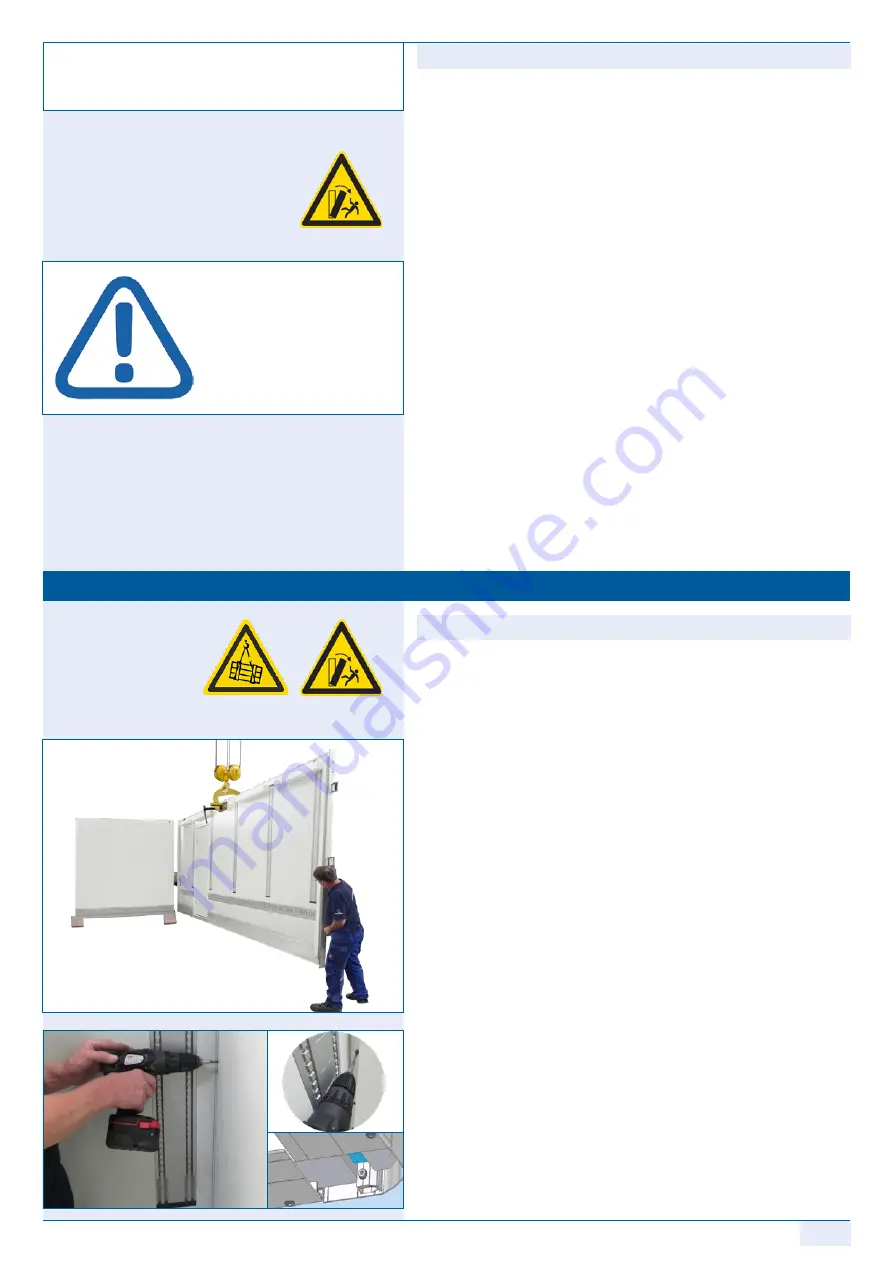
3.1  Assembling the walls

  Use a crane and lifting gear or a vacuum lifting beam to remove the

front wall (bulkhead) from the transport unit and carefully place it 
on the plywood boards. 

Danger:  

Toppling assemblies are at risk to life and limb.


The wall therefore remains secured, e.g. in the crane.

 Remove the first side wall in the same way and push it onto the 

  front wall at right-angles.

Attention:


The corner pillars must not be closed off at the bottom,  


as it may be necessary to lay cables through them later.


  One fitter secures the components on the outside. The 2nd employee

MD100224 (torque 10 Nm ± 1) up to a approx. ¾ of the box height, 
starting at the bottom, until the sections are pressed together. If  
necessary, use punches as an assembly aid.

  Remove the second wall 

(as described above)

  from the transport 

  rack. Position the wall and align it at right-angles with the front 
  wall; the wall remains hanging from the crane initially.

  Now screw in 3 - 4 screws MD100224 again, starting from the bottom

up to approx. ¾ of the box height, until the sections are pressed 
together and the required torque (10 Nm ± 1) is reached.

 3.  Assembling the kit on the floor

AluTeam kits can be assembled in any well-

equipped workshop. Carry out the following 

preparations beforehand.

Attention:


If you use 

adhesives or


sealants other 

than those  


supplied by AluTeam, you  


are responsible for the 


seals and bonding carried  


out with these alternative  


products. 

No warranty

 is 


provided for them.

Содержание BR 248-2

Страница 1: ...arefully before you start the assembly work MA2482 ENG Assembly Instructions BR 248 2 Box Body Kits AluTeam Fahrzeugtechnik GmbH Brockhagener Straße 88 D 33649 Bielefeld Tel 49 0 521 41 73 11 0 Fax 49 0 521 41 73 11 90 E Mail info aluteam de www aluteam de ...

Страница 2: ...he following warnings otherwise the war ranty is voided If you ordered a steel frame or another custom design it is possible that individual work steps are not explained here Note coloured rep resentations are for illustration purposes only Get in touch with us immediately in case of uncertainties 1 1 Checking the kit contents Check the delivery against the enclosed packing list for completeness N...

Страница 3: ...ety goggles when working with air screwdrivers grills grinding equipment etc Wear a helmet when working with or near a crane when unloading transporting the kit in the transport rack using a crane use a suitable lifting beam If using a forklift truck push the transport rack completely onto the fork arms Place transport racks on level surfaces only and secure them against tilting and toppling secur...

Страница 4: ...ng load limit and vacuum lifting beam or lifting gear o 4 wooden panels approx 300 x 300 mm 20 mm stark or similar o Hammer 500 g Punch d 3 mm and d 4 mm o 2 standing ladders or scaffold unit o HSS drill bit Ø 5 0 mm shorter than the wall thickness o Painter s putty knife 2 3 Tightening torques for screws and bolts You only join the components together directly After setting it the named power scr...

Страница 5: ... crane and lifting gear or a vacuum lifting beam to remove the front wall bulkhead from the transport unit and carefully place it on the plywood boards Danger Toppling assemblies are at risk to life and limb The wall therefore remains secured e g in the crane Remove the first side wall in the same way and push it onto the front wall at right angles Attention The corner pillars must not be closed o...

Страница 6: ...he pointed tip facing down wards sideways into the frame crossmember If applicable insert the side lights into the crossmember Screw the gusset plates with 2 screws MD 100227 and plain washers 10 5 mm each by hand so that they are slightly tightened Lift the roof with the single stud fittings or the vacuum lifting beam Centre the roof starting from the front on the top rail of the front wall bulkh...

Страница 7: ...ightening torque of 10 Nm 1 Nm vertically into the side walls front wall connection until the sections are pressed together Fill the remaining cavity between the front wall and side wall panel with the piece of cut foam supplied Then close off the vertical front inside body corners with the corner covers using the rivets MD150023 Screw the remaining screws MD100318 with the ring seal MD110044 into...

Страница 8: ...and the rivet head The connection of the walls to the roof and the corner cover The connections of the top frame crossmember to the pillars The seals should only be pressed in and smoothened with smoothing agent or water without soap additives If necessary the joint between the side door and the floor must also be sealed 3 7 Positioning on the underbody or chassis Fasten the box body onto the subs...

Страница 9: ...and the body must be sealed The body builder is solely responsible for this the After mounting the box body on the substrukture latch the cover into the bottom rail section drawing on the left Insert the cover into the clean cleaned bottom groove and knock or press it in from one end starting from the top Depending on the kit length this is a task for 2 employees Attention If box bodies are unpain...

Страница 10: ...the supplied features pull the connection cable for the side lights out of the frame pillar and use the adapter cable supplied to connect it to the connection cable of the respective vehicle manufacturer Connecting the interior lighting to the chassis s the sole respon sibility of the body builder Always follow the body guidelines of the chassis manufacturer After assembling the box body please on...

Страница 11: ... to the steel and or stainless steel com ponents of the frames A PUR foam core can be incinerated in thermal waste treatment plants without polluting the environment Plywood like particle boards can be burned in wood fired furnaces with at least 50 kW nominal heat output They are subject to stricter carbon monoxide limits than solid wood These values are mostly only achieved by automatically loade...

Страница 12: ... Screws M 12 x 45 MD100307 for connecting the aluminium pillars to the bottom frame crossmember o 2 x corner covers for the vertical front body inside corners o Depending on features 2 x galvanised frame gusset plates bolted type as corner connector for the integrated frame o Ifnecessary 2piecesofcutfoamforthecavitybetweenthefrontwall and the side wall o Plugs for bolting holes in the frame pillar...

Отзывы: