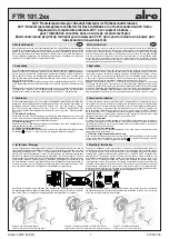
Um den Einstellbereich Einzuengen, wird der sich unter dem Einstellknopf befindliche Stift
abgezogen und die Einstellfahnen verstellt (rot für maximal und blau für minimal mögliche
Einstellung). Anschließend wird der Stift wieder eingesteckt und somit die Begrenzungen
arretiert.
5. Klemmen- und Bediensymbole
5. Terminal and control symbols
Bediensymbole
I
Ein
0
Aus
Automatikbetrieb
Komfortbetrieb
ECO-Betrieb
(Nachtabsenkung)
Betriebsart
Heizen
(am Schalter) Betriebsart Kühlen
(an der Skala) Frostschutzstern (entspricht ca. 5°C)
Wohlfühlpunkt (entspricht ca. 20°C)
Klemmensymbole
L
Phase
Betriebsspannung
N
Neutralleiter
Betriebsspannung
Ausgang
Heizen
Ausgang
Kühlen
ECO-Eingang
(Nachtabsenkeingang)
Control symbols
I
ON
0
OFF
Automatic
mode
Comfort
mode
ECO mode (night temperature decrease mode)
Heating
mode
(at the switch) Cooling mode
(at the scale)
Frost protection system (equivalent to approx. 5°C)
Well-being point (equivalent to approx. 20°C)
Terminal symbols
L
Operating voltage (phase)
N
Operating voltage (neutral conductor)
Output
“heating”
Output
“cooling”
Temperature decrease input (ECO input)
4. Technische Daten
Fühlerelement:
Bimetall, Typ 1C
Versorgungsspannung und Schaltspannung: 24 V~/
4
Heizkontakt:
1(1)A
Kühlkontakt:
1(1)A
Regelbereich:
5 … 30°C
Schaltdifferenz:
ca. 0,5 K
Skala:
Merkziffernskala ( 2 3 5 6)
max. zulässige Temperatur-Änderungs-
geschwindigkeit der Regelstrecke:
4 K/h
Schutzart:
IP30 nach entsprechender Montage
Schutzklasse:
III
max. zulässige Luftfeuchtigkeit:
95%rH, nicht kondensierend
Gehäuse: Berlin
Unterputz
Gehäusematerial und -Farbe:
Kunststoff Polycarbonat (PC),
reinweiß (ähnlich RAL 9010)
Approbation: VDE
siehe
Geräteaufdruck
4. Technical data
Sensing element:
bimetal sensor, type 1C
Supply and switching voltage:
24 V~/
4
Heating contact:
1(1)A
Cooling contact:
1(1)A
Control range:
5 … 30°C
Switching difference:
approx. 0.5 K
Scale:
note numeral scale ( 2 3 5 6)
Max. admissible temperature changing
speed of the controlled system:
4 K/H
Degree of protection:
IP30 (after according installation)
Protection class:
III
Max. admissible air moisture:
95% r.h., non condensing
Housing: design
Berlin
“UP”
Housing material and colour:
plastic (polycarbonate), pure white
(similar to RAL 9010)
Certification:
VDE, see housing imprint
Einstellfahne für
maximalen
Temperaturwert
Einstellfahne für
minimalen
Temperaturwert
Setting pin for
maximum
temperature
limitation
Setting pin for
minimum
temperature
limitation
The setting pins located underneath of the adjusting knob enable to delimit the setting ran-
ge of the controller mechanically. To enable this, the adjusting knob must be removed by
pulling it off and, after the adjustment of the related pins (end stops, red for max. and blue
for min. setting) be put on again in order to lock the limitations.
Только специалисту-электрику разрешается открывать данное устройство и осуществлять
его установку согласно соответствующей схеме соединений на крышке корпуса / корпусе
/ в руководстве по эксплуатации. При этом должны выполняться существующие правила
техники безопасности. Фирма, осуществившая установку устройства, проводит затем
инструктаж персонала эксплуатационной организации по вопросам функционирования
и обслуживания регулятора. Руководство по эксплуатации должно храниться в месте,
легкодоступном для обслуживающего персонала и специалистов по техобслуживанию.
Consigne de sécurité
Указание по безопасности
RUS
Uniquement des personnes qualifiées en matière d’électricité doivent ouvrir ce dispositif
en conformité avec le schéma des connexions représenté dans le couvercle du boîtier /
apposé sur le boîtier / représenté dans les notices d’instructions. Tous électriciens spé-
cialisés chargés de l’exécution de tels travaux doivent se conformer aux prescriptions de
sécurité actuellement en vigueur s’y rapportant. La société chargée de l’installation du dis-
positif doit, après l’achèvement des travaux, initier l’utilisateur aux fonctions du régulateur
et à son opération correcte. Toujours garder cette notice d’instructions à un lieu librement
accessible pour les opérateurs et hommes de service.
1. Application
1.
Применение
Этот регулятор температуры помещения был специально разработан для регулирования
и контроля температуры в офисах, жилых помещениях и гостиницах. Электрические
теплые полы должны иметь дополнительный силовой контактор. При этом следить за тем,
чтобы из-за мощности отопления также и в длительном режиме работы не перегревался
бесшовный пол. В случае водяного отопления или водяного охлаждения использовать не
более 5 закрытых в обесточенном состоянии клапанов.
Внимание!
У регулятора типа
FTR 101.265
, разработанного специально для 2-трубных
систем кондиционирования, отметки на переключателе нагрева/охлаждения рассчитаны
на закрытые в обесточенном состоянии клапаны. Возможно необходимые ограничители
температуры должны быть установлены дополнительно. Для других, не предусмотренных
производителем областей применения необходимо соблюдать правила техники
безопасности, действующие в соответствующей области. Пригодность для этого см. в
пункте 7. Гарантия.
Ce régulateur de température ambiante a été spécialement conçu pour le réglage ou surveil-
lance de températures dans des bureaux, habitations et hôtels. Des systèmes de chauffage
par le sol électriques doivent être excités par un contacteur de puissance additionnel. Avec
ces systèmes il faut veiller à assurer à ce que la puissance du système contrôlé ne puis-
se, même si le système est opéré en marche continue, résulter dans une surchauffe de la
structure superficielle correspondante. Avec des systèmes de chauffage à eau chaude ou de
refroidissement à eau ne plus que 5 soupapes du type normalement fermées doivent être
utilisées.
Attention!
Avec le type de régulateur FTR 101.265 spécialement conçu pour le ré-
glage de systèmes de climatisation à 2 conduites, l’empreinte sur le commutateur inverseur
«chauffer/refroidir» se réfère aux soupapes du type normalement fermé. Le cas échéant,
l’installation de limitateurs de température est nécessaire de plus. En ce qui concerne
d’autres applications pas à prévoir par le fabricant de ce dispositif, les standards de sécuri-
té se rapportant à ces applications sont à respecter. Quant à l’aptitude ou l’approba tion du
dispositif pour des telles applications, veuillez également tenir compte des informations de
garantie dans chapitre 7. (Garantie) dans cette notice d’instructions.
2
F


