background image

ALPINE ELECTRONICS, INC.

Tokyo office: 1-1-8 Nishi Gotanda,

Shinagawa-ku, Tokyo 141-8501, Japan

Tel.: (03) 3494-1101

ALPINE ELECTRONICS OF AMERICA, INC.

19145 Gramercy Place, Torrance,

California 90501, U.S.A.

Tel.: 1-800-ALPINE-1 (1-800-257-4631)

1-888-NAV-HELP (1-888-628-4357)

ALPINE ELECTRONICS OF CANADA, INC.

Suite 203, 7300 Warden Ave. Markham,

Ontario L3R 9Z6, Canada

Tel.: 1-800-ALPINE-1 (1-800-257-4631)

1-888-NAV-HELP (1-888-628-4357)

ALPINE ELECTRONICS OF AUSTRALIA PTY. LTD.

6-8 Fiveways Boulevarde Keysborough,

Victoria 3173, Australia

Tel.: (03) 9769-0000

ALPINE ELECTRONICS GmbH

Kreuzerkamp 7-11

40878 Ratingen, Germany

Tel.: 02102-45 50

ALPINE ITALIA S.p.A.

Via C. Colombo 8, 20090 Trezzano Sul

Naviglio MI, Italy

Tel.: 02-48 47 81

ALPINE ELECTRONICS FRANCE S.A.R.L.

(RCS PONTOISE B 338 101 280)

98, Rue De La Belle Etoile, Z.I. Paris Nord Il

B.P. 50016 F-95945, Roissy,

Charles De Gaulle Cedex, France

Tel.: 01-48 63 89 89

ALPINE ELECTRONICS OF U.K., LTD.

13 Tanners Drive, Blakelands,

Milton Keynes MK14 5BU, U.K.

Tel.: 01908-61 15 56

ALPINE ELECTRONICS DE ESPAÑA, S.A.

Portal De Gamarra 36, Pabellón 32

01013 Vitoria (Alava)-Apdo. 133, Spain

Tel.: 34-45-283588

Designed by ALPINE Japan

Printed in Japan (Y)

68P30540Y46-O

Yamagata Printing
Co., Ltd.
2-6-34, Takashima,
Nishi-ku, Yokohama,
Kanagawa, Japan

NVE-N077P

Guide for Installation and Connections

Guide d’installation et de connexion

Guía de instalación y conexiones

Installations- und Anschlußanleitung

Guida all’installazione e al collegamento

Handleiding voor installatie en aansluiting

Nederlands

Italiano

Deutsch

Español

Français

English

Voice Navigation System

Содержание NVE-N077P

Страница 1: ...taly Tel 02 48 47 81 ALPINE ELECTRONICS FRANCE S A R L RCS PONTOISE B 338 101 280 98 Rue De La Belle Etoile Z I Paris Nord Il B P 50016 F 95945 Roissy Charles De Gaulle Cedex France Tel 01 48 63 89 89...

Страница 2: ...TION SUCH AS THE STEERING WHEEL OR SHIFT LEVER Doing so may obstruct forward vision or hamper movement etc and results in serious accident DO NOT DAMAGE PIPE OR WIRING WHEN DRILLING HOLES When drillin...

Страница 3: ...HED BY A SHARP METAL EDGE Route the cables and wiring away from moving parts like the seat rails or sharp or pointed edges This will prevent crimping and damage to the wiring If wiring passes through...

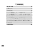
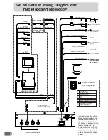
Страница 4: ...NVE N077P Wiring Diagram With TME M750 7 3 2 NVE N077P Wiring Diagram With IVA C800R IVA M700R CVA 1005R 8 3 3 NVE N077P Wiring Diagram With CVA 1000R 9 3 Mounting 12 4 Confirmation 14 3 4 NVE N077P W...

Страница 5: ...flection type or thermal absorption type glass may interrupt high frequency waves If reception is poor with the aerial installed inside the car try to mount the aerial outside the car Aerial Aerial 1...

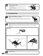
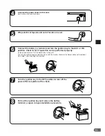
Страница 6: ...al Note Some vehicles contain a vehicle control computer etc in this case contents of the computer memory may be erased when the battery lead is disconnected Water proof pad 6 1 Cut terminal leads as...

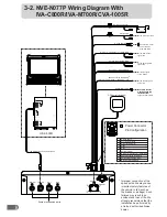
Страница 7: ...on White Blue Parking Brake Yellow Blue Reverse Orange White Mute Pink Skyblue 13P RGB Extension Cable Included Speed Sensor Green White Connect to VSS Digital or Analog 0V 3V A A Acc Ignition Red 2 M...

Страница 8: ...In Illumination White Blue Parking Brake Yellow Blue Reverse Orange White Mute Pink Skyblue 13P RGB Extension Cable Included Speed Sensor Green White Connect to VSS Digital or Analog 0V 3V A A Acc Ig...

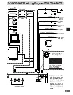
Страница 9: ...io Mute System expansion ports VOLUME MUTE SOURCE CVA 1000R SET UP V SEL SYSTEM CONTROL MONITOR RECEIVER 35Wx4 TFT COLOR LCD FUNC R D S EON Yellow Blue Parking Brake Input White Blue Dimmer Red Igniti...
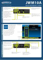
Страница 10: ...0V 3V A A Acc Ignition Red 2 Mute Pink Sky blue 3 Open 4 Open 5 Battery Yellow 6 Dimmer In Illumination White Blue 7 Speed Sensor Green White 8 Parking Brake Yellow Blue 9 Reverse Orange White 10 1 6...

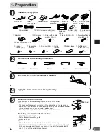
Страница 11: ...tion can be performed properly Is the power turned on Is the illumination turned on You can check the language selection menu with the monitor Refer to the Owner s Manual for details Go to step 7 afte...

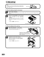
Страница 12: ...o the adhesive on the Velcro strips Press the Navigation unit onto the mounting location Continued to 5 Securing leads etc a When mounting on the rear tray Mount the brackets 1 on the unit Mount the b...

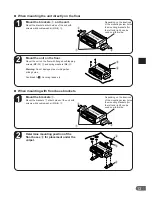
Страница 13: ...the floor with flanged self tapping screws M5 15 5 and spring washers M6 6 Warning Do not damage pipe or wiring when drilling holes Continued to 5 Securing leads etc 5 6 a When mounting with floor ba...

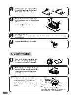
Страница 14: ...sure the unit is operating correctly by referring to the Owner s Manual ON Make sure the electrical components attached on the vehicle such as the brake lamp stop lamp etc work correctly a Remote con...

Отзывы: