background image

AlphaFeverCamera  

Quick Start Guide 


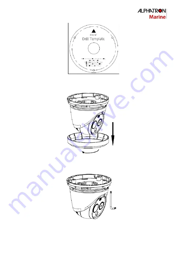
Figure 3-3 Drill Template 

2.


Turn the ring anticlockwise and remove it. 

Note

: The ring is only applicable to type II camera. 

Figure 3-4 Remove the Ring 

3.


Loosen the screw and dismount the camera body from the base. 


Figure 3-5 Dismount the Camera from Base 

4.


Mount the camera base according to the position of drill template. 

Содержание AlphaFeverCamera

Страница 1: ...AlphaFeverCamera Network Turret Camera alphatronmarine com...

Страница 2: ...ference that may cause undesiredoperation EU Conformity Statement This product and if applicable the supplied accessories too are marked with CE and comply therefore with the applicable harmonized Eur...

Страница 3: ...IEC60950 1 standard SELV Safety Extra Low Voltage and the Limited Power Source 12 VDC Refer to the appropriate documentation for detailed information DO NOT connect multiple devices to one power adap...

Страница 4: ...lated environment Keep non waterproof devices away from liquids Keep the device in original or similar packaging while transportingit A few device components e g electrolytic capacitor require regular...

Страница 5: ...4 Install Network Cable Water proof Jacket 8 3 4 1 Install Network Cable Waterproof Jacket 8 3 4 2 Waterproof Other Cables 9 4 Set the System over the LAN 10 4 1 Wiring 10 4 2 Activate the System 10 4...

Страница 6: ...th the Cat5 in 100M or Cat6 100M above isneeded When the Turret Camera uses standard 12V DC power supply the power cable should be American wire gauge 18 or above The formula of the cross section S mm...

Страница 7: ...e I camera and Type IIcamera 2 1 Type I Turret Camera Appearance Refer to the following figure for type I thermal turret camera overview Figure 2 1 Type I Thermal Turret Camera Overview 2 2 Type II Tu...

Страница 8: ...onnections This section is only for the Turret Camera with alarm in out functions The Turret Camera can be connected with alarm inputs 0 5VDC and alarm outputs Refer to the following diagrams for alar...

Страница 9: ...unction and remote focus function For different lens focal length the monitoring range is shown in the table below Table 3 1 Monitor Range Pixel Interval 17um Lens Focal Length mm 1 8 3 1 6 2 MRAD 9 4...

Страница 10: ...s 1 Remove the cover on the back of the TurretCamera Figure 3 1 Remove the Cover 2 Insert the SD card to the SD card slot and install the cover back Figure 3 2 SD Card Slot 3 3 Install Turret Camera T...

Страница 11: ...anticlockwise and remove it Note The ring is only applicable to type II camera Figure 3 4 Remove the Ring 3 Loosen the screw and dismount the camera body from the base Figure 3 5 Dismount the Camera...

Страница 12: ...pan direction 0 360 or rotate the lens in the tilt direction 0 80 to get the desired view angle 0 360 0 80 Figure 3 7 Mount the Camera Body 6 Screw the screw to fix the camera body on the camera base...

Страница 13: ...or tapes to waterproof the cables Otherwise the cables might get wet or a short circuit occurs 3 4 1 Install Network Cable Waterproof Jacket Steps Figure 3 10 Install Waterproof Jacket 1 Feed the netw...

Страница 14: ...he in clockwisedirection 3 4 2 Waterproof Other Cables After routing and connecting the cables use the waterproof tapes to wrap up the cables Connected cables and spare cables both should be wrapped u...

Страница 15: ...you need to connect the network system in the same subnet with your PC Then install the SADP or client software to search and change the IP of network system The following figure shows the cable conne...

Страница 16: ...the password Get the SADP software from the supplied disk or the official website and install the SADP according to the prompts Follow the steps to activate the system Steps 1 Run the SADP software to...

Страница 17: ...to search and change the IP of network system We will take modifying the IP Address via SADP software as an example to introduce the IP address modification Steps 1 Run the SADPsoftware 2 Click to se...

Страница 18: ...device IP address to the same subnet with your computer by either modifying the IP address manually or checking the checkbox of Enable DHCP Figure 4 4 Modify the IP Address 4 Input the password and c...

Страница 19: ...nput the IP address of the network Turret Camera e g 192 168 1 64 and press the Enter key to enter the login interface 3 Activate the Turret Camera for the first time using refer to the section 4 2 Ac...

Страница 20: ...the web browser after the installation of the plug in and repeat the above steps 2 4 to login Note For detailed instructions of further configuration please refer to the user manual of network Turret...

Страница 21: ...ively Click to display the help file of the Turret Camera Click to logout the system Live View Window Display the live video Toolbar Operations on the live view page e g live view capture record audio...

Страница 22: ...1 Common Material Emissivity Reference Material Emissivity Human Skin 0 98 PCB 0 91 Cement Concrete 0 95 Ceramics 0 92 Rubber 0 95 Paint 0 93 Wood 0 85 Asphalt 0 96 Brick 0 95 Sand 0 90 Soil 0 92 Cott...

Страница 23: ...s therequirements Select the power supply as close as possible Examine the power cord and see whether it meetsthe requirements 6 2 2 Device Upgrading Question Device fails to upgrade Answer Examine if...

Страница 24: ...vice orset manual mapping to port No 80 8000 or 554 Examine if the live view channel amount exceeds the upper limit Examine the networkbandwidth Question Focus fails when you test outdoor device in in...

Отзывы: