3. SIDE PANEL
13
SIDE PANEL
3.1
AC Power Cord
The AC power cord plugs directly into the enclosure’s convenience outlet. Since the
power module does not have an ON/OFF switch, the utility circuit breaker should be used
as the main switch. In situations where the power supply is to be completely powered
down, first switch the battery breaker OFF. This will prevent the unit from going into
inverter operation when utility AC is removed.
3.2
Standby Status Relay (optional)
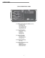
On APM and USM units equipped with the SSR (Standby Status Relay), a dry
“Form C” contact accommodates systems requiring remote alarms. The left connector (1)
white is configured as common. The right connector (2) red is configured “normally open”
(contacts close when alarm is present). For special applications, contact 2 can be config-
ured “normally closed” (contacts open when alarm is present) by repositioning the wire
located on the module's back plane board from position P104 to P105.
3.3
Remote Indicator Lamp (optional)
The LRI lamp, used in conjunction with the APM (Automatic Performance Monitor),
plugs directly into the REMOTE INDICATOR LAMP connector. The connector fits in one
direction only with the wiring configuration clearly marked for easy identification. The
(negative) wire is connected to the left side of the connector (3) black. The (positive) is
connected to the right (4) red. The LRI circuit is rated at 24 VDC, 250mA. Use only Alpha
P/N 740-139-20 (24 Volt LRI Lamp and Socket).
3.4
AC Output
The SPI (Service Power Inserter), which couples output power to the load, plugs
directly into the AC OUTPUT connector. The connector is color-coded and fits in one
direction only with the wiring configuration clearly marked for easy identification. The
(neutral) wire is located on the left side of the connector (5) white; the (hot) on the right (6)
black.
NOTE: ACI OPTION
The ACI option is an external indicator of the XM power module's AC output status
(see page 16). If the ACI is included in the installation, the lamp's connector plugs directly
into the power module's output (5 & 6). The SPI then plugs into the second connector
located on the ACI lamp assembly.
3.5
Battery Connector
The batteries plug directly into the power module's battery connector. The connector is
color-coded and fits in one direction only. Note: Always verify proper polarity of cables
before connecting the batteries to the power module. Polarity is clearly marked for easy
identification. The red cable (+) is located on the left side of the connector; the black cable
(-) on the right. If, for some reason, the cables become interchanged at the batteries, the
battery circuit breaker will trip.
3.6
AC Output Fuse
The AC output fuse prevents short circuit current from entering the load. Fuses are
rated according to the particular model: (XM6015 = 20 A 250V; XM6012 / XM6012 E = 15
A 250V; XM6010 / XM6010 E = 12 A 250V). NOTE: If the green "AC OUTPUT" LED
located in the front panel SYSTEM STATUS block is OFF, indicating no AC output, check
this fuse.


