6.4
Connecting Utility Power
CAUTION: THE FOLLOWING SHOULD BE PERFORMED ONLY BY QUALIFIED SERVICE
PERSONNEL AND IN COMPLIANCE WITH LOCAL ELECTRICAL CODES. CONNECTION
TO UTILITY POWER MUST BE APPROVED BY THE LOCAL UTILITY BEFORE INSTALL-
ING THE POWER SUPPLY.
NOTE: UL AND NEC REQUIRE THAT A SERVICE DISCONNECT SWITCH (UL LISTED) BE
PROVIDED BY THE INSTALLER AND BE CONNECTED BETWEEN THE POWER SOURCE
AND THE ALPHA POWER SUPPLY. CONNECTION TO THE POWER SUPPLY MUST
INCLUDE AN APPROPRIATE SERVICE ENTRANCE WEATHER HEAD.
WIRING THE ENCLOSURE’S UTILITY SERVICE
Utility power enters the enclosure through a 1 1/8" opening at the bottom of PME, UPE
and UPE/M, and the rear of PWE. The enclosure accepts a standard electrical fitting. The
UPE is equipped with a service entrance mounted in the small compartment at the bottom
of the enclosure. The PME and PWE are equipped with a circuit breaker assembly located
in the enclosure’s module compartment. UPE/M is equipped with a dedicated utility
raceway.
IMPORTANT NOTE: A high-magnetic 15 Amp circuit breaker must be used in
order to accommodate the high inrush currents normally associated with the start-up
of ferroresonant transformers (400 Amp, no-trip, first-half cycle). Do not replace this
breaker with a conventional service entrance breaker.
High-magnetic circuit breakers for Square D service entrances are available from Alpha
Technologies.
Description
Alpha Part No.
Square D
High Inrush Breaker
470-013-10
Q0115HM
Ext. Serv. Disconnect
020-085-10
Q02-4L70RB
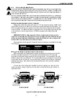
Wiring: (From duplex receptacle to service disconnect)
Alpha enclosures are equipped with a duplex receptacle to provide power to the UPS
and other peripheral equipment. The receptacle should protected by a 15 Amp, high
magnetic circuit breaker located inside the service disconnect. The receptacle's hot side
(black) is wired to the circuit breaker. The neutral (white) and ground (green) connect to the
service disconnect's neutral bus. A grounding clamp, located on the enclosure, facilitates
dedicated grounding. Note: Refer to the drawings at the back of the manual for detailed
wiring information.
In most cases, this configuration qualifies for service entrance use, however, other
codes may apply. Always contact your local utility to verify that the wiring conforms to
applicable codes.
Neutral
AC
Line
Utility Grounding Clamp
on underside of enclosure
Ground (green)
Chassis Ground
Neutral
AC
Line
Utility Grounding Clamp
on underside of enclosure
120 VAC (60 HZ)
230 VAC (50 HZ)
Ground (green)
Ground (green)
Outlet
Outlet
AC Line (brown)
AC Line (brown)
Neutral
(blue)
AC Line (black)
AC Line (black)
Neutral
(white)
Utility
Ground
Chassis Ground
Ground
Ground
23
6. INSTALLATION
Typical Circuit Breaker Assembly


