010-619-J0 Rev B
Page 16
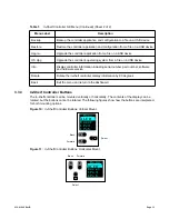
front panel. A full defragmentation may take up to 20 minutes to perform, do not power down the
controller during this time.
NOTE
:
Refer also to the software manual – always select the Reset menu item before pressing the reset
button.
3.4.5
Ethernet Port
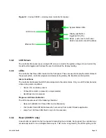
The Ethernet port is designed for connection to a user supplied network (TCP/IP secured by user) via
a front panel RJ-45 jack and a standard network cable.
Local access (e.g. laptop computer) is also possible from the Ethernet port connection using a standard
network cable.
3.4.6
Analog Input Channels
The controller is provided with analog input channels for voltage, current, and temperature.
Voltage Inputs
Two voltage input channels, V1 and V2, provide monitoring of discharge and charge voltage. The
controller software is pre-configured to monitor V1 for battery voltage and V2 for load voltage.
V2 is wired internally to the rectifier shelf to provide a reference for rectifier float voltage, low voltage
disconnect (LVD), system high voltage alarm, and system low voltage alarm.
Wire V1 to battery to monitor battery voltage or change battery setting from V1 to V2 in
Signals >
Configure Signals
.
Current Inputs
The controller software is pre-configured to monitor I1 for battery current wired internally to the battery
current shunt.
Temperature Inputs
Two temperature input channels, T1 and T2, provide monitoring of battery temperature and temperature
compensation (temp comp) or room/ambient temperature. A voltage is supplied to these terminals to
power the temperature sensors.
3.4.7
Digital Input Channels
The controller can accommodate up to two channels and can monitor digital alarm/control signals from
rectifiers, converters and many other types of equipment.
3.4.8
Alarm and Control Output Relays
The controller contains seven Form C digital alarm output relays to extend alarms and control external
apparatus. Each internally generated alarm or control signal may be mapped to any one of the relays,
or, several signals may be mapped to just one relay or none at all.
3.4.9
Network Connection and Remote Communication
The Cordex system can be set up, monitored and tested via an Ethernet connection. The communica-
tion protocol supports a web interface. All alarming and control of Cordex rectifiers is accomplished with
a controller via a CAN bus.
Содержание Cordex HP 48 1.2kW
Страница 2: ......
Страница 4: ......
Страница 10: ...vi...
Страница 14: ...010 619 J0 Rev B Page 4...
Страница 16: ...010 619 J0 Rev B Page 6 Figure 1 Single Shelf Figure 2 Dual Shelf Figure 3 2RU Shelf...
Страница 28: ...010 619 J0 Rev B Page 18...
Страница 30: ...010 619 J0 Rev B Page 20...
Страница 46: ...010 619 J0 Rev B Page 36...
Страница 56: ...010 619 J0 Rev B Page 46...
Страница 58: ...010 619 J0 Rev B Page 48...


