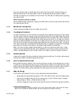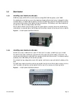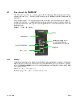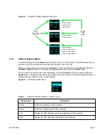
010-619-J0 Rev B
Page 15
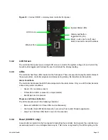
Figure 12:
Cordex CXCM1+ model system controller front panel
3.4.2
LCD Screen
The controller front panel uses a 4-digit LCD screen to monitor the system voltage (V) and current (A).
A push-button toggle switch allows the user to alternate the display reading.
3.4.3
LEDs
The controller has three LEDs located on the front panel. These are used to display the alarm status of
the power system, controller progress and status during startup, file transfers and lamp tests.
Alarm Conditions
The controller illuminates the LED that corresponds to the alarm status. Only one LED is illuminated at
a time during alarm conditions:
•
Green: OK, no alarms present
•
Yellow: Minor alarm is present (no major alarms)
•
Red: Major alarm is present.
Progress and Status Indication
The LEDs are also used in the following situations:
•
Base unit validation: All three LEDs on simultaneously
•
File transfer: Red LED illuminates when recovering from invalid firmware application
•
Lamp Test: All three LEDs flash in sync for two seconds
3.4.4
Reset (CXCM1+ only)
A reset button is located on the front panel for restarting the controller. During reset, the controller may
occasionally need to run a defragmentation cycle. This can be recognized by the LEDs cycling on the
System Status LEDs
LCD Screen
Display pushbutton
toggle switch (V/A)
Ethernet Port
Reset - push once for soft reset
Hold 3 seconds to reset IP address
Содержание Cordex HP 48 1.2kW
Страница 2: ......
Страница 4: ......
Страница 10: ...vi...
Страница 14: ...010 619 J0 Rev B Page 4...
Страница 16: ...010 619 J0 Rev B Page 6 Figure 1 Single Shelf Figure 2 Dual Shelf Figure 3 2RU Shelf...
Страница 28: ...010 619 J0 Rev B Page 18...
Страница 30: ...010 619 J0 Rev B Page 20...
Страница 46: ...010 619 J0 Rev B Page 36...
Страница 56: ...010 619 J0 Rev B Page 46...
Страница 58: ...010 619 J0 Rev B Page 48...


