010-619-J0 Rev B
Page 8
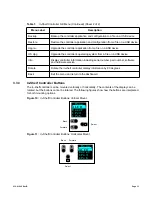
When the “locate module” command has been received from the controller, the LEDs behave in a
distinctly different way so that the rectifier is easier to visually identify among adjacent rectifiers.
This state is entered when commanded via the controller. The LEDs flash in a distinct pattern repeating
every two seconds.
LED Activity During Firmware Upload
When a rectifier firmware upload is in progress, the LEDs behave in the same way as the locate module
command described above.
3.1.3
Mechanical Locking Clip
A locking clip automatically secures the rectifier into the shelf.
3.1.4
True Module Fail Alarm
The power modules have a “true” fail alarm. This provides a true indication of the power module’s ability
to source current. When the module’s output current drops below 2.5% of the rated output a low output
current condition is detected and the Module Fail detection circuit is activated. This circuit momentarily
ramps up the output voltage to determine if the module will source current. If no increase in current is
detected, the Module Fail alarm is activated. The module will test once every 60 seconds for the condi-
tion until current is detected. Output voltage ramping will cease upon detection of current
1
. A minimum
2.5% load is required to avoid the Ramp Test Fail alarm; this can typically be provided with the parallel
system battery. Activation of this alarm could indicate a failed module or a failed load.
NOTE
:
For Cordex rectifier systems without batteries (or with a very light load; below 2.5% of rated
output) it is recommended that the ramp test be disabled to avoid nuisance alarms. The Ramp Test
feature is enabled/disabled via the controller. Refer to the software manual for detailed information.
3.1.5
Heat Dissipation
Cooling of the module is front-to-rear with the exhaust air exiting at the back. The fan is variable speed;
which is determined by heatsink temperature and load.
3.1.6
Over Temperature Protection
Each rectifier module is protected in the event of an excessive increase in temperature due to compo-
nent failure or cooling airflow blockage. During over temperature conditions, the rectifier limits the output
power as well as the output current. If temperature continues to increase, a shutdown of the rectifier is
initiated. The rectifier shall restart automatically if the temperature has returned to a safe level.
3.1.7
Wide AC Range
A minor alarm is generated when the AC input voltage drops below specification.
•
Output power is reduced linearly between 176Vac and 132Vac to 60% of the rated output power.
•
Input current is limited to less than 6A for operation from 132Vac to 90Vac. Power is derated
linearly between 132Vac (~700W) to 90Vac (~475W).
•
At a lower voltage the module will shut down and will not restart until the AC is greater than 90Vac.
1. Under normal conditions, a battery connected to the output of the rectifier will draw current when the voltage
ramp occurs. Therefore the rectifier fail alarm will not be generated with a battery connected.
Содержание Cordex HP 48 1.2kW
Страница 2: ......
Страница 4: ......
Страница 10: ...vi...
Страница 14: ...010 619 J0 Rev B Page 4...
Страница 16: ...010 619 J0 Rev B Page 6 Figure 1 Single Shelf Figure 2 Dual Shelf Figure 3 2RU Shelf...
Страница 28: ...010 619 J0 Rev B Page 18...
Страница 30: ...010 619 J0 Rev B Page 20...
Страница 46: ...010 619 J0 Rev B Page 36...
Страница 56: ...010 619 J0 Rev B Page 46...
Страница 58: ...010 619 J0 Rev B Page 48...


