ADM-PCIE-8K5-FH User Manual
Table 5
PCIe Reference Clocks ..................................................................................................................... 7
Table 6
Fabric Clock ....................................................................................................................................... 8
Table 7
EMCCLK ............................................................................................................................................ 8
Table 8
SFP+ Reference Clocks .................................................................................................................... 8
Table 9
FireFly Reference Clocks .................................................................................................................. 9
Table 10
Memory Reference Clocks ................................................................................................................ 9
Table 11
FireFly Part Numbers ....................................................................................................................... 12
Table 12
Voltage, Current, and Temperature Monitors ................................................................................... 13
Table 13
Status LED Definitions ..................................................................................................................... 14
Table 14
Complete Pinout Table ..................................................................................................................... 21
List of Figures
Figure 1
ADM-PCIE-8K5-FH Product Photo .................................................................................................... 1
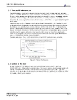
Figure 2
Thermal Performance ........................................................................................................................ 3
Figure 3
8K5-FH With Attached Optional Blower ............................................................................................. 4
Figure 4
ADM-PCIE-8K5-FH Block Diagram ................................................................................................... 4
Figure 5
Switches ............................................................................................................................................ 5
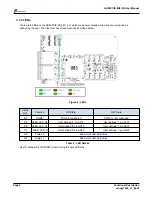
Figure 6
LEDs .................................................................................................................................................. 6
Figure 7
Clock Topology .................................................................................................................................. 7
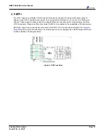
Figure 8
SFP Locations .................................................................................................................................. 11
Figure 9
FireFly Locations ............................................................................................................................. 12
Figure 10
Timing Input Schematic ................................................................................................................... 15
Figure 11
SFP Locations ................................................................................................................................. 15
Figure 12
Flash Address Map .......................................................................................................................... 16
Figure 13
GPIO Connector .............................................................................................................................. 18


