Installation & Systems Manual RUBIDIUM SERIES
Page 62
3.27
VM
: Continuous Wave Distribution Amplifier
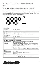
This module distributes and amplifies one continuous wave input to six outputs. A seventh
spare output stage together with a change-over relay at each of the six outputs enables
complete redundant output signals. Each output stage is monitored for signal failures. Alarm
outputs are available as SNMP, GPI, LEDs and lamps.
AlVelte
SIG IN
INPUT
OUT 2
OUT 6
OUT 4
OUT 1
OUT 5
OUT 3
GPI OUT
8 . . . . . 1
1 . . . . . 8
Signal input
:
Connector
BNC (IEC169-8), 75
DC range
5 V
Input impedance
75
Ω
Signal specifications
Frequency range: 10 MHz
5
%,
Amplitude range: 0.2 – 2.5 Vpp signal input at 75
Ω
Signal outputs
:
Connector
BNC (IEC169-8), 75
Output impedance
75
Ω
Gain
1 ± 1
%
GPI_1 to GPI_7 outputs, indicating failures
:
Output specification
Open Collector output of a NPN Darlington transistor.
Max. power dissipation: 200 mW.
“High” state
“High” state: External pull-up needed to a positive power source of
less than or equal to 30 VDC, typically 1 k
Ω
when connected to an
ex5 VDC power source.
“Low“ state
“Low“ state: Output switched to GND. Maximum collector current =
200 mA DC, not fused.
Collector-emitter saturation voltage: @100 mA: typ. 0.9 V (
1.1 V).
Others
:
Operating voltage
12 - 30 VDC
Power consumption
1.6 W maximum (GPI_1 – GPI_7 unconnected)
Weight
0.5 kg approx.
Mechanical
2 circuit boards (W x D): 100 x 160 mm / 3.94 x 6.30 inch
Rear panel: RUB H1: 103 x 44 mm / 4.06 x 1.73 inch
RUB H3: 8HP, 3RU
Содержание RUBIDIUM
Страница 2: ......
Страница 15: ...Installation Systems Manual RUBIDIUM SERIES Page 15 A6 EC Declaration of Conformity...

