4 - INSTALLATION
4.4 CONNECTION OF THE P.T.O. JOINT
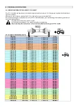
The angle of the P.T.O. shaft position must be at the minimum (not exceeding 10°–15°), by respecting such position
both shaft and machine will definitely last longer (see fig. below).
CONNECT THE UNIVERSAL JOINT WITH A P.T.O. HAVING
R.P.M. COMPATIBLE WITH THE ONES MARKED ON THE
STICKERS APPLIED ON THE MACHINE OR WITH THE
VALUES LISTED IN THE CHART OF CHAPTER 2
Since the P.T.O. shaft is a part that rotates at a sustained speed, it is balanced by the manufacturer during final
testing. Any modifications could cause imbalance which might influence operation of the machine and integrity of the
shaft.
When the P.T.O. shaft is withdrawn to the maximum, in every kind of working condition, the telescopic tubes must
overlap for at least 1/3 of their length.
When fully inserted, the shaft must be loose by a minimum of 4 cm.
If this is not possible, contact the After Sales Technical Service of the manufacturing company.
Before starting up the machine, make sure that the safety chains are on the protecting guards to prevent them from
rotating with the P.T.O. shaft. Check that the guards are in perfect condition.
Read carefully the instruction manual supplied by the P.T.O. shaft manufacturer.
If worn out or broken, replace P.T.O. shaft with a new one marked
The P.T.O. shaft manufacturer does not recommend modifications. It is therefore forbidden to make
any modification or adjustments of any kind on the P.T.O. shaft.
4.5
TRACTOR LIFTING ABILITY AND STABILITY CHECK
Whenever an extra tool is coupled with a tractor, according to public road rules and regulations this
becomes an integral part of the tractor, stability could be altered causing difficulty when driving and
operating it.
Coupling of a machine with a tractor involves a different distribution of the
weights on the axes. It is recommended therefore to add special
ballasts/weights at the front of the tractor to distribute the weight adequately on
the axes. The correct weight of the ballasts must be calculated using the
following formula:
M x s < 0,2 T x i + Z ( d + i )
( M x s ) – ( 0,2 T x i )
Z > -----------------------------------------------------------
( d + i )
where:
i = distance between the axes of the tractor wheels [m]
d = distance between the front axis and the front ballasts [m]
s = overhanging from rear axis of the equipment [m]
T = mass weight of tractor [Kg]
Z = mass weight of ballasts [Kg]
M = mass weight of the equipment [Kg]
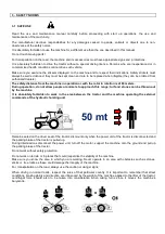
At least 20% of the total mass weight of the t
machine must be balanced on the front axle of the
tractor.
It is very important to follow the instructions given by
the manufacturer when coupling the tractor and the
machine together and when applying ballasts on the
front of the tractor because these hints can help you
improve the stability of the tractor.
When tractor is not being used, the machine must
be ALWAYS lowered onto the ground to avoid
unintentional descents, and at the same time to
maintain the correct stability.
Distance between the axes of the tractor wheels
i =……………… m
Distance between front axle and front ballasts
d =………………m
Overhanging from rear axis of the machine
s =………….. ….m
Mass weight of tractor
T =………………Kg
Mass weight of ballasts
Z =………………Kg
Mass weight of equipment
M =……………...Kg
Содержание T10 Series
Страница 31: ...6 MAINTENANCE ...

