background image


53 

2.10


System Configuration 

The

 System Configuration

 page provides the management information  for the switch. The page 

shown below can be activated by clicking the 

Setup 

menu under the System section. 


The following parameters can be configured / displayed: 

n


IP Address 

– the IP address used to manage this switch through the configuration port.   

n


Subnet Mask

 – the network mask to identify the sub-network address 

n


Default Gateway 

– the IP address of the default gateway to reach to the outside network 

n


MAC Address – 

the MAC address for the configuration port interface (read-only)


n


Firmware Version – 

the current version of firmware running in the switch (read-only)


Содержание GSS-8T2SFP

Страница 1: ...1 ALLOY 8 Port Gigabit Web Smart Switch GSS 8T2SFP User s Manual Version 1 0 6 Oct 12 2004...

Страница 2: ...19 2 6 Trunk 22 2 6 1 Trunking Rules 23 2 6 2 Get Refresh the Latest Trunk Settings 24 2 6 3 Enable Trunk 25 2 6 4 Modify Trunk Settings 26 2 6 5 Disable Trunk 27 2 7 Port Mirroring 28 2 7 1 Get Refr...

Страница 3: ...10 1 Get Refresh the Latest Address Management Settings 49 2 10 2 Add a New Entry 50 2 10 3 Modify an Existing Entry 51 2 10 4 Delete an Existing Entry 52 2 11 System Configuration 53 2 12 Account Set...

Страница 4: ...Ethernet port Cfg Port is supported for initial setup The out of band Ethernet port provides an independent control channel which is secure from the main network It can optionally be connected back to...

Страница 5: ...n is provided for the last two shared ports for copper fibre connection n 1 5M bit packet buffer n 4K MAC entries n Support for port based VLAN and tag based 802 1Q VLAN n MAC based trunk with fail ov...

Страница 6: ...witch unless one gigabit port is linked to the configuration port Try to PING the switch from your PC to make sure the network connection is successful The IP address on this switch can be modified la...

Страница 7: ...Port VLAN Configures port based VLAN s n 802 1Q VLAN Configures tag based VLAN s n Trunk Enable and configure Trunkning n Mirror Setup port mirroring functions n QOS Configure Quality of Service funct...

Страница 8: ...Rx through the port Tx Only enable packet forwarding from this port Packet receiving is not allowed Rx Only enable packet reception on this port Packet forwarding is not allowed Disable Block all traf...

Страница 9: ...ired result ie Port 3 cannot communicate with port 4 but Port 3 can communicate with port 1 n Jumbo Frame Shows the current settings for Jumbo Frame capability as Enabled Disabled for this port Jumbo...

Страница 10: ...configured read only n Enable Option Tx Rx Enable bi directional traffic for the port Tx Enable one way only forwarding traffic for the port Rx Enable one way only receiving traffic for the port Disa...

Страница 11: ...age Click the Back button to abort the modifications 2 2 About the Copper Fibre Media Auto Detection The switch provides 2 optional mini GBIC SFP ports for use with either copper or fibre modules Thes...

Страница 12: ...nts The switch supports up to 8 port based VLAN groups for manual entry The following pages will describe in detail how to configure port based VLAN s NOTE A default port based VLAN entry No 1 is init...

Страница 13: ...he next available The switch administrator needs to add the VLAN Port Members After you have completed your configuration press the Submit button you will then be redirected back to the VLAN initial s...

Страница 14: ...lete button As shown in the figure above there are 2 port based VLAN groups 1 and 2 Check the radio button at the head of each row and press the Delete Button The result is shown in the following figu...

Страница 15: ...ed VLAN group first check the radio button of the group you want to edit and click the Edit button Then set the member Ports 7 and 8 Press the Submit button to complete the Edit function The port base...

Страница 16: ...the 802 1Q VLAN menu This page provides the following functions to configure the 802 1Q VLAN n Enable Disable VLAN n Frames which VID s are not in the VLAN table n 802 1Q control per port configurati...

Страница 17: ...emember to click the Apply button to activate and save the settings to the switch 2 4 2 Frames for which VID is not in VLAN Table There are two options provided to make the system manipulate the frame...

Страница 18: ...parameters to determine the 802 1Q tag contents Non 1Q Frame This determines what will occur to packets that do not match the 802 1Q VID assigned to this port Options are Drop to drop the non matchin...

Страница 19: ...x beside the port number in the Untagged Members row Checkboxes in the Untagged Members row can only be configured when the corresponding checkboxes in the Members row are selected In the example belo...

Страница 20: ...LAN entries as shown below To delete the 802 1Q VLAN entry click a radio button on the Select column e g Entry No 2 VID 285 then click the Delete button to do perform the deletion Once the above has b...

Страница 21: ...erform the modifications VID is changed to 333 and port 1 and port 8 are selected to be members of this group Then select the port 1 as a Untagged Member for the 802 1Q VLAN entry Finally click the Ap...

Страница 22: ...p fails or is disconnected If a port within the trunk group fails the other ports of the trunk group assume the traffic load automatically The following parameters are required to be set n Enable Disa...

Страница 23: ...d n All trunk member ports must be in the same group in Port VLAN and 802 1Q VLAN functions n After enabling a trunk group a symbol will be marked before the port numbers which belong to the trunk gro...

Страница 24: ...24 2 5 2 Get Refresh the Latest Trunk Settings Click the Trunk menu on the web page to review the current trunk settings on the switch...

Страница 25: ...ose the member port s up to 4 within a trunk group Step 2 Check the corresponding checkbox for these member ports ex port1 port2 port4 port5 Step 3 Click the Enable radio button Step 4 Click the Apply...

Страница 26: ...unk Settings Step 1 Choose the member port s up to 4 within the trunk group Step 2 Check the corresponding checkbox for these member ports ex port3 port4 port6 Step 3 Click the Apply button to modify...

Страница 27: ...27 2 5 5 Disable Trunk Step 1 Uncheck the checkboxes Step 2 Click the Disable radio button Step 3 Click the Apply button to disable the trunk...

Страница 28: ...of any other port s Several filter rules are used to avoid congestion when multiple ports are mirrored at the same time Port Mirroring can be configured to capture ingress and or egress traffic of a p...

Страница 29: ...re are five options for each port Capture to set the corresponding port to be a capture monitoring port Ingress Egress to set the corresponding port to be a monitored port to investigate bi directiona...

Страница 30: ...ort ex port2 Step 2 Check the corresponding checkbox for monitored ports ex port4 Ingress Egress port6 Ingress Only port8 Egress Only and other ports OFF Step 3 Click the Enable radio button Step 4 Cl...

Страница 31: ...irror Settings Step 1 Change the capture or monitored ports ex port3 Capture port5 Ingress Egress port7 Ingress Only port8 Egress Only and other ports OFF Step 2 Click the Apply button to modify the m...

Страница 32: ...32 2 6 4 Disable Mirror Step 1 Click the Disable button Step 2 Click OFF for all ports Step 3 Click the Apply button to disable mirroring...

Страница 33: ...r frames with a destination address matching the Ingress Egress MAC Address n Ingress Egress MAC Address Enter the specific MAC address that you want to monitor n Ingress Egress Divider Enter the spec...

Страница 34: ...ess MAC Address 0A 0B 0C 0D 0E 0F Step 3 Enter Ingress Divider as 5 and enter Egress Divider as 8 Step 4 Click the Apply button to activate the mirroring filter settings Result Every fifth frame with...

Страница 35: ...35 2 6 7 Disable Mirror Filter Step 1 Change Ingress Egress Filter to All Frames Step 2 Set Ingress Egress Divider equal to 0 Step 2 Click the Apply button to modify mirroring filter settings...

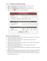
Страница 36: ...Q Control Per Port Config 802 1P QOS arranges packet in to one of four transmit queues by priorityof ingress packet with 802 1Q VLAN tag MAC Based QOS arranges packets in to one of four transmit queue...

Страница 37: ...er queues in weighted round robin mode Weighted Round Robin Transmit all packets in weighted round robin mode n QOS Type Port Based QOS Enable port based QOS type 802 1P QOS Enable 802 1P QOS type Not...

Страница 38: ...le QOS Step 1 Choose the Transmit Queue Algorithm ex Highest Queue Preempt Step 2 Choose the QOS Type ex Port Based QOS Step 3 Click the Enable radio button Step 4 Click the Apply button to enable the...

Страница 39: ...39 2 7 3 Modify QOS Settings Step 1 Choose the Transmit Queue Algorithm ex Weight Round Robin Step 2 Choose the QOS Type ex 802 1P QOS Step 3 Click the Apply button to modify QOS settings...

Страница 40: ...40 2 7 4 Disable QOS Step 1 Click the Disable button Step 2 Click the Apply button to disable QOS...

Страница 41: ...e switch will be displayed The parameters provided are n Priority ID to Tx Queue ID Map Enter the corresponding Tx Queue ID 0 3 for each Priority ID n 802 1p Priority Level to Priority ID Map Enter th...

Страница 42: ...t queue id equal to 1 the transmit queue with low priority 3 All packets with priority id equal to 4 5 and 6 will be stored in transmit queue id equal to 2 the transmit queue with high priority 4 All...

Страница 43: ...et 1 could monitor unicast packets Multiple packet types can be monitored by each bucket and a packet type can be monitored by both buckets The Bucket bit rate can be set by the rate count which range...

Страница 44: ...ding traffic based on the rate value of the ingress port For example traffic flows from port1 to port2 ordinary link speed 1000Mbps for both ports and the rate control is enabled on port1 with rate va...

Страница 45: ...roadcast packets n Destination Lookup Fail Used to apply Rate control to packets whose destination addresses DA don t exist in the switches address table for lookup These packets are normally broadcas...

Страница 46: ...it Config for Bucket 0 page is shown below The field Ingress Rate 1 125 is an integer that increments decrements the ingress rate at a given port and must be specified on a per port basis After you en...

Страница 47: ...based on the different rates in different link speeds 10 100 1000Mbps Link Speed Rate 10Mbps 100Mbps 1000Mbps 100 10Mbps 100Mbps 1000Mbps 80 8Mbps 80Mbps 800Mbps 64 6 4Mbps 64Mbps 640Mbps 56 5 6Mbps 5...

Страница 48: ...switch and a 802 1Q VLAN is not enabled the GSS 8T2SFP will search for the MAC address in the address table according to the MAC address If a 802 1Q VLAN is enabled the GSS 8T2SFP will search this MA...

Страница 49: ...e web page the latest Address Management settings on the switch will be displayed The following options are provided n Add Add a new entry into the static MAC entry table n Delete Remove an existingen...

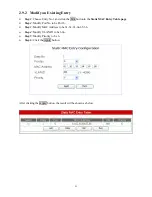
Страница 50: ...tep 2 Choose the Port No e g Port 3 Step 3 Enter the MAC Address e g 31 32 33 34 34 36 Step 4 Enter the VLAN ID e g 3333 Range 1 4094 Step 5 Choose the Priority e g Priority 3 After clicking the Apply...

Страница 51: ...tonin the Static MAC Entry Table page Step 2 Modify Port No to be Port 6 Step 3 Modify MAC Address to be 61 62 63 64 65 66 Step 4 Modify VLAN ID to be 666 Step 5 Modify Priority to be 6 Step 6 Click t...

Страница 52: ...9 3 Delete an Existing Entry Choose a desired entry to be removed e g entry1 and click the Delete buttonto complete the deletion After deletion the content in the Static MAC Entry Table will be refre...

Страница 53: ...n be configured displayed n IP Address the IP address used to manage this switch through the configuration port n Subnet Mask the network mask to identify the sub network address n Default Gateway the...

Страница 54: ...password for login validation The switch provides only one login account for configuration management Click the Account menu to activate the Account Setting page shown below n User Name Set the userna...

Страница 55: ...GSS 8T2SFP also provides two alternatives to perform a Reboot after Write Default option by using the Reset buttonon the front panel of the switch While the system is running the DIAG LED indicator i...

Страница 56: ...available Please refer to the instruction guide for setting up the BOOTP server The firmware filename file location and the IP address to assign to the switch are three important parameters to setup t...

Страница 57: ...erent IP domains 8G Smart Switch C 1 2 3 4 5 6 7 8 NMS PC1 192 168 1 100 PC2 192 168 1 200 IP 192 168 2 254 Switch Traffic 192 168 1 10 192 168 2 10 Config Traffic The advantages of out of band manage...

Страница 58: ...xample for in band switch management 8G Smart Switch C 1 2 3 4 5 6 7 8 NMS 192 168 1 100 PC2 192 168 1 200 Config Traffic IP 192 168 1 254 Switch Traffic The advantage of in band management is that an...

Отзывы: