506162-02
Issue 0847
Page 10 of 14
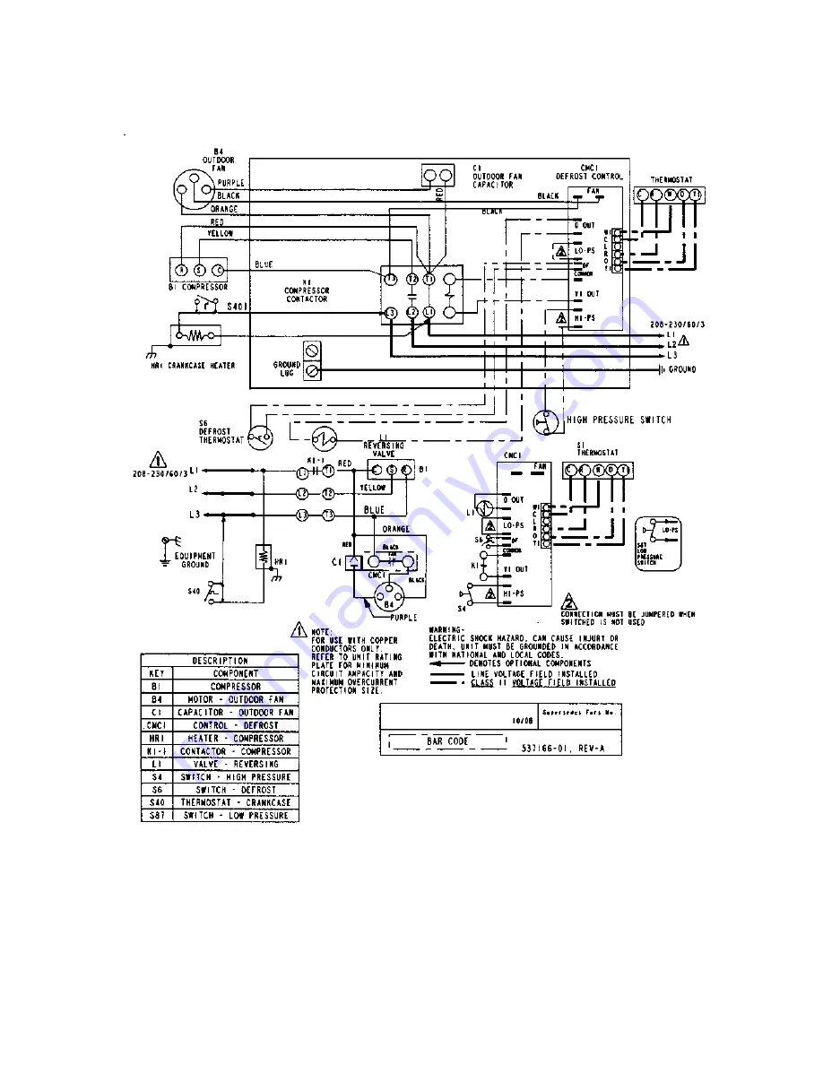
H/P 3 PHASE WIRING DIAGRAM
Страница 1: ...l Code Part 1 CSA C22 1 2HP13 14 4HP13 SPLIT SYSTEM HEAT PUMP INSTALLATION START UP INSTRUCTIONS HOMEOWNERS INFORMATION MANUAL TABLE OF CONTENTS These units are designed for use in residential and light commercial type buildings Heat Pumps may only be installed with indoor combinations listed in the Air Conditioning and Refrigeration Institute ARI Directory of Certified Products Inspect the unit f...
Страница 2: ...nnected to factory approved indoor unit outdoor unit contains system refrigerant charge for operation with indoor unit of the same size when connected by 15 ft of field supplied tubing For proper unit operation check refrigerant charge using charging information located on control box cover IMPORTANT Maximum liquid line size is 3 8 in O D for all residential applications including long lines Outdo...
Страница 3: ...rant line lengths DO NOT LOCATE THE UNIT On brick concrete blocks or unstable surfaces Near clothes dryer exhaust vents Near sleeping area or near windows Under eaves where water snow or ice can fall directly on the unit with clearance less than 2 ft from a second unit with clearance less than 4 ft on top of unit Operating Ambient The minimum outdoor operating ambient in cooling mode is 55 F and t...
Страница 4: ...th water using a wet rag Leave rag on fitting body and re wet with water to help cool area Leak Check Refrigeration lines and indoor coil must be checked for leaks after brazing and before evacuation The recommended procedure is to apply a trace amount of vapor refrigerant approximately two ounces or 3 psig into the line set and indoor coil then pressurize with 150 psig of dry nitrogen Use a refri...
Страница 5: ... at the line side of the contactor in the control box of the outdoor unit Follow the appropriate wiring diagram attached to inside of the access panel Proper circuit protection recommendations are indicated on Unit Rating Plate Time delay fuses are required to prevent blowing due to starting current the current in rush when equipment starts is referred to as the Locked Rotor Amps or LRA A fuse of ...
Страница 6: ...or line sets shorter than 15 feet in length remove charge For line sets longer than 15 feet add charge Oil charge is sufficient for all line lengths Before final adjustment is made to the refrigerant charge it is imperative that proper indoor airflow be established Airflow will be higher across a dry coil versus a wet coil Blower charts are calculated with a dry or wet coil basis Recommended airfl...
Страница 7: ...ously Filter Drier The outdoor unit is equipped with a bi flow filter drier If replacement is necessary order new dryer according to the service parts manual Emergency Heat Function Room Thermostat An emergency heat function is designed into some room thermostats This feature is applicable when isolation of outdoor unit is required or when auxiliary electric heat is staged by outdoor thermostats W...
Страница 8: ... seconds going in and out of the defrost mode when the compressor delay jumper is removed NOTE The 30 second off cycle is not functional when jumpering the TEST pins Time Delay The timed off delay is 5 minutes long The delay help to protect the compressor from short cycling in case the power to the unit is interrupted or a pressure switch opens The delay is bypassed by placing the timer select jum...
Страница 9: ...506162 02 Issue 0847 Page 9 of 14 H P SINGLE PHASE WIRING DIAGRAM ...
Страница 10: ...506162 02 Issue 0847 Page 10 of 14 H P 3 PHASE WIRING DIAGRAM ...
Страница 11: ... manufacturers The information below is typical for most thermostats Ask your dealer for specific information regarding the model of thermostat installed Temperature Setting Levers Most heat pump thermostats have 2 temperature selector levers one for heating and one for cooling Set the levers or dials to the desired temperature set points for both heating and cooling Avoid frequent temperature adj...
Страница 12: ...s dryers and fall off from trees can be drawn into coils by movement of the air Clogged condenser coils will lower the efficiency of your unit and could cause damage to the condenser Periodically debris should be brushed from the condenser coils Use a soft bristle brush with light pressure only DO NOT damage or bend condenser coil fins Damaged or bent fins may affect unit operation Painted Surface...
Страница 13: ...lete model and serial number b proof of required periodic maintenance installation date and location c an accurate description of the problem W ARRANTY LIMITATIONS 1 This warranty is void if the covered equipment is removed from the original installation site 2 This warranty does not cover damage or defect resulting from a flood wind fire lightning mold or installation and operation in a corrosive...
Страница 14: ...506162 02 Issue 0847 Page 14 of 14 NOTES ...