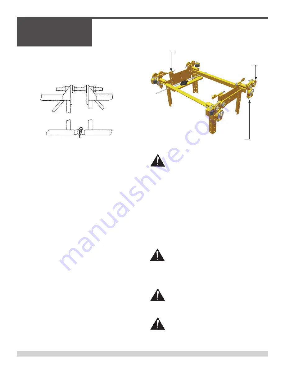
4. MACHINE LEG ADJUSTMENT
- You can now lift the
machine onto the prepared deck. Adjust the machine legs so
that the leg span distance is the same as the center to center
distance between the machine screed rails. Adjust the length of
the machine legs so that the carriage will clear the deck or slab
when the machine is placed on the rails. Position the carriage
toward the idler end of the machine so that the machine will be
balanced when it is lifted. Position the bogie wheels for clearance
of the reinforcing steel.
the machine is split the power unit section is self supporting
and stable. Hook up the idler end of the machine to a lifting device.
Remove the crown bolts at the top of the truss frame and the hinge
pins on the lower end of the truss frame.
Crown Bolt Assembly
Truss Connection
The idler insert section will now be free to lift and placed to the side.
Add or remove the required frame inserts on the power unit insert and
reconnect the idler end section of the machine. Keep the frame as
straight as possible. When attaching the inserts together it is suggest-
ed that you lubricate the crown bolts. If the deck or slab has a crown,
assemble the machine so that an insert hinge will be directly above
the crown. The manual crown adjuster will have to be removed and
relocated to the correct place on the machine for crowning the truss
frame. When the sections have been assembled reconnect the carriage
travel chain, release the paving carriage and add the additional bogie
hose for the machine bogie wheels on the idler end of the machine.
2. INSTALLING PAVING CARRIAGE
- If it is necessary to
install the paving carriage use the following procedure:
A) With the paving carriage setting on blocks, remove
the carriage hanger frame and install the frame into
truss. Move the machine over the top of the paving
carriage so that the paving carriage is centered under
the machine truss. Using the leg cranks, lower the
machine down until the carriage hanger frame can be
bolted back on to the carriage. Position the carriage
in the middle of the machine and connect the travel
chain. Adjust the hold down roller tension so that the
rollers can be just turned by hand. The carriage travel
chain will keep the carriage from moving when the
machine is lifted onto the deck.
3. BOGIE INSTALLATION
- Prepare the machine for lifting (See
Lifting Instructions) and lift the machine high enough to install
the machine leg bogies on to the machine legs. Install the drive
bogies on the rear side and the idler bogies on the front side of
the machine. The drive chain shield can be on the outside or the
inside of the leg, depending on clearance requirements. If nec-
essary, add the additional hose provided with new frame inserts.
CAUTION! Make sure that the hydraulic hoses are
connected so that the direction of machine travel
is the same as indicated on the control console. If
necessary, reverse the hose connections at the quick
disconnect fittings to correct travel direction.
Chain Tensioner
Tension Set Screw
Hold Down Roller
WARNING! Use extreme caution when lifting the pav-
ing machine. Make sure the lifting device has enough
capacity to lift the weight of the machine. Check
all chains, slings, lifting cables, clevises and cable
clamps for strength and for any structural damage.
WARNING! Keep all personnel away from the machine
while it is being lifted.
WARNING! Before lifting the machine, check to make
sure that the Machine Legs are LOCKED! If the legs
are not locked they could roll causing an unbalanced
lift and personal injury.
SECTION 2
OPERATIONS
050362
Page 32
2.5 - Machine Setup, continued
Содержание BDF4836B
Страница 5: ...050362 Page 5 Table of Contents continued ...
Страница 14: ...050362 Page 14 Notes ...
Страница 15: ...SECTION 1 SAFETY 050362 Page 15 SECTION 1 SAFETY ...
Страница 21: ...SECTION 1 SAFETY 050362 Page 21 PAGE LEFT BLANK INTENTIONALLY ...
Страница 22: ...Notes SECTION 1 SAFETY 050362 Page 22 ...
Страница 23: ...SECTION 2 OPERATIONS 050362 Page 23 SECTION 2 OPERATIONS ...
Страница 40: ...Power Crown Lever Nut A SECTION 2 OPERATIONS 050362 Page 40 2 6 Power Crown Option ...
Страница 46: ...Skew Clamp Skew Cylinder SECTION 2 OPERATIONS 050362 Page 46 2 7 Paving Operations continued ...
Страница 49: ...SECTION 2 OPERATIONS 050362 Page 49 PAGE LEFT BLANK INTENTIONALLY ...
Страница 50: ...SECTION 2 OPERATIONS 050362 Page 50 Notes ...
Страница 51: ...SECTION 3 SERVICE 050362 Page 51 SECTION 3 SERVICE ...


