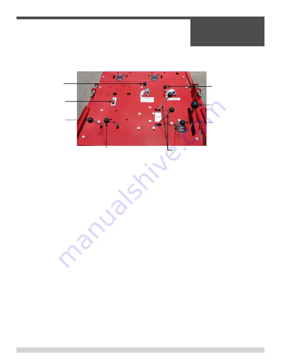
PAVER CONTROLS
BEFORE STARTING ENGINES READ THE ENGINE STARTING
INSTRUCTIONS AND ALL WARNING DECALS LOCATED ON
THE OPERATORS CONSOLE AND AT OTHER KEY POINTS ON
THE MACHINE.
Both carriage travel and machine travel are controlled from the opera-
tor’s control console as well as optional accessories.
A. Manual Carriage Directional Control
Can be used to change the direction of the carriage travel. When
the carriage directional control is moved in either direction from the
center position the carriage travel speed begins to slow down. To
reverse the direction of the carriage travel move the control all the
way in the direction of the desired travel. Move the control lever with a
smooth, steady motion to avoid erratic carriage travel starts and stops.
A different method to reverse travel is to stop the carriage travel using
the Power Selector Control. Move the Power Selector Control to the
“Stop” position. Reverse the carriage travel by moving the Carriage
Directional Control in the desired travel direction and then return the
Power Selector Control to the “Pave” position.
CAUTION: WHEN THE CARRIAGE DIRECTIONAL CONTROL
IS MANUALLY HELD IN EITHER DIRECTION THE CARRIAGE
WILL CONTINUE TO TRAVEL IF (A) THE POWER SELECTOR
CONTROL IS IN THE “PAVE” POSITION, (B) THE MACHINE
TRAVEL DIRECTION CONTROLS ARE ENGAGED AND (C) THE
MACHINE TRAVEL SPEED CONTROL IS NOT SET AT ZERO.
B. Power Selection Control
The power selection valve has three functions, Pave, Stop and
Travel. To avoid erratic carriage travel, slowly ease the control to each
new position. In the “Pave” position the carriage will move back and
forth through the machine truss. The “Pave” position provides power to
the carriage travel drive and delivers power for the automatic machine
travel drive. The machine travel drive will be triggered each time the
carriage automatically reverses direction.
CAUTION: BEFORE ENGAGING CARRIAGE TRAVEL BE SURE
THAT ALL PERSONNEL ARE CLEAR OF THE PAVING CAR-
RIAGE. THE PAVING CARRIAGE WILL NOT AUTOMATICALLY
REVERSE DIRECTION OF TRAVEL WHEN IT REACHES THE END
OF THE MACHINE UNLESS THE CARRIAGE TRAVEL REVERS-
ING LUGS ARE INSTALLED ON THE CARRIAGE TRAVEL CHAIN.
FOR INSTRUCTIONS SETTING THE REVERSING LUGS SEE
SECTION III - “SET-UP” INSTRUCTIONS.
The “Stop” position is used when starting the power unit engine and to
automatically stop all functions. The “Travel” position is used for man-
ually moving the machine in either the forward or the reverse direction.
Manual Carriage Direction
Power Selector Valve
Machine Travel Speed
Machine Travel Direction Controls
Carriage Travel Speed
Power Crown (Option)
ACC Power
Water Spray (Option)
SECTION 2
OPERATIONS
050362
Page 25
2.2 - Machine Control Detail
Содержание BDF4836B
Страница 5: ...050362 Page 5 Table of Contents continued ...
Страница 14: ...050362 Page 14 Notes ...
Страница 15: ...SECTION 1 SAFETY 050362 Page 15 SECTION 1 SAFETY ...
Страница 21: ...SECTION 1 SAFETY 050362 Page 21 PAGE LEFT BLANK INTENTIONALLY ...
Страница 22: ...Notes SECTION 1 SAFETY 050362 Page 22 ...
Страница 23: ...SECTION 2 OPERATIONS 050362 Page 23 SECTION 2 OPERATIONS ...
Страница 40: ...Power Crown Lever Nut A SECTION 2 OPERATIONS 050362 Page 40 2 6 Power Crown Option ...
Страница 46: ...Skew Clamp Skew Cylinder SECTION 2 OPERATIONS 050362 Page 46 2 7 Paving Operations continued ...
Страница 49: ...SECTION 2 OPERATIONS 050362 Page 49 PAGE LEFT BLANK INTENTIONALLY ...
Страница 50: ...SECTION 2 OPERATIONS 050362 Page 50 Notes ...
Страница 51: ...SECTION 3 SERVICE 050362 Page 51 SECTION 3 SERVICE ...


