BRIDGE DECK FINISHER SET-UP GUIDE - 069596
Page 9
BDF Assembly & Set-up
• The depth and penetration required will vary according to
job specifications.
• Pitching the front end of the drum higher allows the roller
tamper to remain parallel to the concrete surface when the
rear of the machine is raised at the beginning of the pour,
with the max recommended depth is 3/16 inch.
CARRIAGE TRAVEL DISTANCE
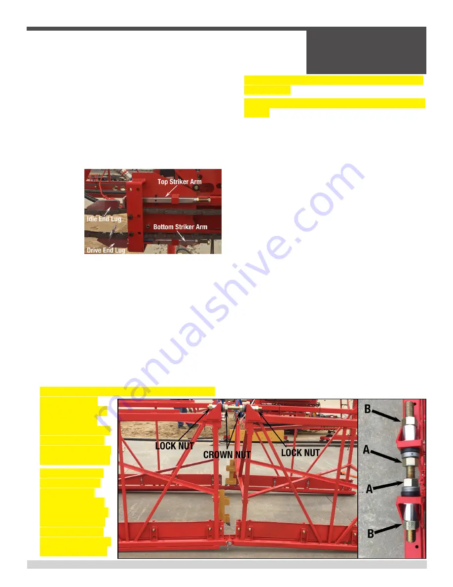
• Adjust the carriage travel distance by positioning the chain
lugs on the
upper and
lower travel
chains (SEE
PICTURE).
• Manually
push with
your hand,
the top striker
plate of the shifter until the reversing valve shifts. Manually
push with your hand, the bottom striker plate of the shifter
until the reversing valve shifts. Do this for both directions of
carriage travel.
• Place the paving carriage at the desired travel distance at
the idler end of the machine and stop the carriage. Hold
back the striker plate and attach the chain lug next to the
striker plate on the top of the travel chain.
• Place the paving carriage at the desired travel distance at
the power unit end of the machine and stop the carriage.
Hold back the striker plate and attach the chain lug next to
the striker plate on the bottom of the travel chain.
• Once the chain lugs have been installed, to set the paving
carriage pivot shift
movement on the idle
end, slide a striker
target or shifter paddle
onto the carriage rail
at the desired point the
carriage needs to shift.
• After the shifting rod
makes contact with
target, the paving
roller reversing valve
will not engage at this
time, TO ENGAGE the
shift in the reversing
valve, move the paddle
approximately 1”- 2”,
until the rod spring shifts the reversing valve and the lower
carriage shifts.
• Tighten the T-Bolt to lock the Striker target or shifter paddle
in place.
• REPEAT the previous 3 steps for the power unit side of
the machine.
• The bottom thrust rollers on the hanger frame, positioned
under the carriage rail can be tightened so that the rollers
have a slight pressure on the carriage rail, allowing you to
turn them by hand.
MANUAL / POWER / CROWN BOLT ADJUSTMENT
• The insert frame section hinge point or truss connection
should be positioned on the machine to coincide directly
above the crown center.
• The paving carriage should be moved to the crown position,
allowing for deflection of the truss frame with the full weight
of the carriage.
• Note the measurement from a grade point on the deck to
the top of the carriage rail on both sides of the machine.
• The manual/power/crown bolts can be adjusted for the
machine frame slope to the specified deck crown or center
grade slope (1.5%,2%, 2.5%...).
• For the crown bolts, adjust them ½” at a time and alternate
sides (SEE PICTURE) which allows a slight shift with the
angle change.
• Loosening lock nuts “B” on both sides, allows you to adjust
the crown nuts “A” and vice versa..


