background image

8

     Compact Industrial Non-display Computers

Rockwell Automation Publication 6155R-IN002E-EN-P - July 2013

Install the Computer

The computers support various mounting options:

Wall mount

DIN rail mount

VESA mount

A bracket with mounting screws is provided for each mounting option.

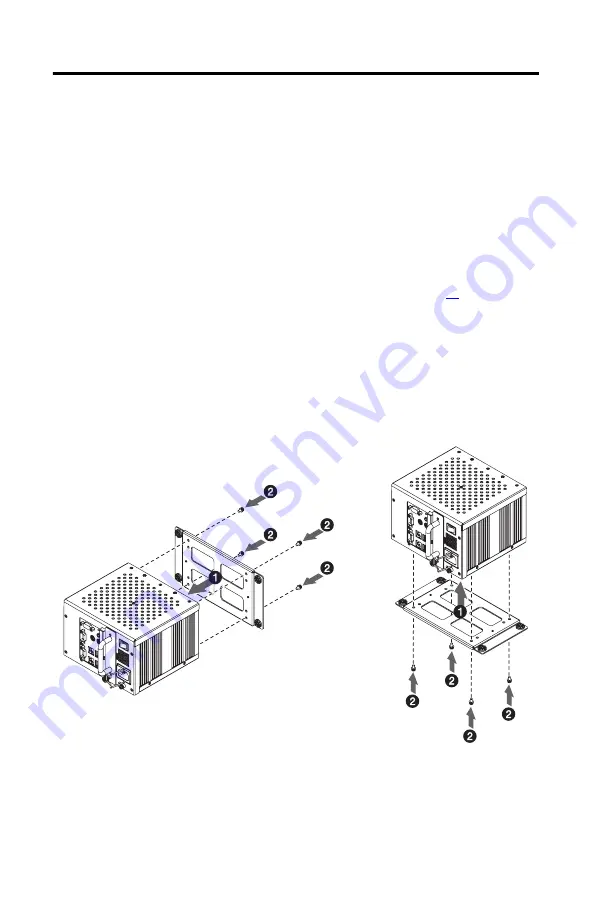
Mount the Computer on a Wall

You can mount the computer on a wall by using a mounting bracket. See page

11

 for the 

wall-mount bracket dimensions. 

1.

Drill and tap four M4 holes in the wall, a minimum of 5 mm, that correspond to the 
holes in the mounting bracket. 

2.

Attach the mounting bracket to the bottom or back of the computer 

(1)

.

3.

Secure the mounting bracket with the provided M4 x 8 mm panhead screws 

(2)

.

Torque the screws to 0.686 N•m (6.072 lb•in).

4.

Position the computer against the wall, aligning the holes in the mounting bracket with 
the holes in the wall 

(3)

.

TIP

Support the computer with a shelf or other means to make installation at the appropriate 
height easier. 

Mounting Bracket on the Back

Mounting Bracket on the Bottom

Содержание 6155F-NPWE

Страница 1: ...55F NPXPDC 6155F NPWEDC Topic Page Important User Information 2 Precautions 3 Computer Options 4 Operating Systems 4 Parts List 5 Hardware Features 6 Install the Computer 8 Connect Peripherals 12 Apply Power 13 Connect to a Network 15 Real time Clock RTC Battery 16 Ship or Transport the Computer 17 Specifications 17 Additional Resources 19 ...

Страница 2: ... particular installation Rockwell Automation Inc cannot assume responsibility or liability for actual use based on the examples and diagrams No patent liability is assumed by Rockwell Automation Inc with respect to use of information circuits equipment or software described in this manual Reproduction of the contents of this manual in whole or in part without written permission of Rockwell Automat...

Страница 3: ...gned to prevent personal injury resulting from accessibility to live parts The interior of the enclosure must be accessible only by the use of a tool UL listed equipmentneednotbemountedinsideanotherenclosure Subsequentsectionsofthispublication may contain additional information regarding specific enclosure type ratings that are required to comply with certain product safety certifications In addit...

Страница 4: ... rotating hard disk drives include a recovery partition on the system drive containing the original factory image You can use the supplied Computer System Cloning CD to restore the operating system from the recovery partition and create a new recovery image Refer to the Cloning Utility technical data publication 6000 TD002 for instructions Computers with Windows Embedded Standard 2009 include a ut...

Страница 5: ...R IN002E EN P July2013 PartsList The computers are shipped with these items Mounting hardware AC power cord for AC power models Ground bus strip pre installed for DC power models Installation instructions Production test report Industrial Computer System Cloning Utility CD red CD ...

Страница 6: ...d Performance models have two serial COM ports 10 Functional ground screw 2 VGA port 11 HDD or SSD 3 PS 2 mouse port 12 CompactFlash Type II card slot 4 HDD or SSD indicator 13 PS 2 keyboard port 5 Power indicator 14 USB ports 4 6 Audio line out jack 15 Ethernet port 2 3 RJ45 3 Standard models have one Ethernet port and Performance models have two Ethernet ports 7 Power switch 16 Serial COM port 1...

Страница 7: ...llow adequate clearance around the computer for ventilation and cable connections When mounted in an enclosure or high temperature area the ambient temperature around the computer must not exceed the operating temperature range Use this clearance For 25 mm 1 in Sides of computer 51 mm 2 in Top of computer 13 mm 0 5 in 1 1 This clearance is not required when provided mounting hardware is used Botto...

Страница 8: ...acket dimensions 1 Drill and tap four M4 holes in the wall a minimum of 5 mm that correspond to the holes in the mounting bracket 2 Attach the mounting bracket to the bottom or back of the computer 1 3 Secure the mounting bracket with the provided M4 x 8 mm panhead screws 2 Torque the screws to 0 686 N m 6 072 lb in 4 Position the computer against the wall aligning the holes in the mounting bracke...

Страница 9: ...he computer on a DIN rail The DIN rail bracket mounts to the back of the computer See page 11 for the DIN rail bracket dimensions 1 Attach the DIN rail bracket to the back of the computer 1 2 Secure the DIN rail bracket by using four M4 x 5 mm panhead screws torque to 0 686 N m 6 072 lb in 2 IMPORTANT Do not mount the computer on a DIN rail in high shock and vibration environments Mounting Bracket...

Страница 10: ...Bradley industrial monitor or other surface by using the provided VESA mounting bracket This bracket is compliant with the VESA 100 x 100 mm mounting hole pattern See page 11 for the VESA mounting bracket dimensions 1 Attach the VESA mounting bracket to the installation surface 1 2 Secure the VESA mounting bracket with the four M4 x 8 mm flathead screws 2 3 Place the computer on the VESA mounting ...

Страница 11: ...6 0 236 114 6 4 512 46 1 811 64 2 52 92 3 622 11 3 0 444 140 5 511 150 5 90 192 7 56 86 3 385 49 1 929 46 1 811 92 3 622 114 4 488 80 3 149 140 5 511 172 6 771 8 5 0 334 16 0 629 14 0 55 22 0 866 100 3 94 156 6 14 100 3 94 176 4 6 945 84 3 318 35 85 1 41 2 0 079 DIN rail Mounting Bracket VESA Mounting Bracket Wall Mounting Bracket All dimensions are in mm in ...

Страница 12: ...s Computer dimensions for the computer are given in mm in ConnectPeripherals Connect the required peripherals such as the keyboard mouse and monitor to the corresponding I O ports on the computer Refer to Hardware Features on page 6 for required connections 158 6 22 115 4 51 158 6 22 172 6 77 Top View Front View Side View ...

Страница 13: ...nel cutout Reattach the clip after installing the computer ConnectACPower A grounded 3 prong IEC320 power cord provides power to a computer with an AC power input The power supply input accepts 100 240V AC and is autoranging 1 Connect the power cord to the AC power input 1 2 Secure it in place with the retention clip 2 Operate the computer in an industrial or control room environment which uses so...

Страница 14: ...upport SELV cases where the end user requires grounding at the computer Follow these steps to connect the computer to a DC power source 1 Turn off the main power switch or breaker 2 Secure the DC power wires to the terminal block screws 3 Secure the DC ground wire to the GND terminal screw 4 Apply 9 36V DC power to the computer ATTENTION Use a Class 2 Safety Extra Low Voltage SELV isolated and ung...

Страница 15: ...LAN ports depending on the model The computer connects to the Ethernet network by using twisted pair Ethernet cabling with RJ45 connectors IMPORTANT TopreventperformancedegradationofEthernetcommunication donotsubjectthecomputer or cables to extreme radiation or conducted high frequency noise Proper cable routing and power conditioning isrequired for reliable Ethernet communication in industrial en...

Страница 16: ...re or short external contacts Do not expose the battery to temperatures higher than 60 C 140 F Do not dispose of a used battery in water or fire For safety information on handling lithium batteries see Guidelines for Handling Lithium Batteries publication AG 5 4 WARNING To prevent voiding your product warranty use only Allen Bradley approved replacement parts and accessories IMPORTANT Replacing th...

Страница 17: ...e it in its original packing material before shipping Rockwell Automation is not responsible for damage incurred to a computer that is shipped or transported while installed in a machine panel or rack Attribute 6155R NSXP 6155R NPXP 6155R NPXPDC 6155F NPXP 6155F NPWE 6155F NPXPDC 6155F NPWEDC Weight approx 5 kg 11 lb Dimensions HxWxD approx 115 x 172 x 158 mm 4 51 x 6 77 x 6 22 in excluding handle...

Страница 18: ... 1 g peak 57 640 Hz 0 012 in p p 10 57 Hz 2 g peak 57 640 Hz Vibration nonoperating 1 0 012 in p p 10 57 Hz 2 g peak 57 640 Hz Attribute 1 1 See http www rockwellautomation com rockwellautomation certification overview page for declarations of conformity certificates and other certification details 6155R NSXP 6155R NPXP 6155R NPXPDC 6155F NPXP 6155F NPWE 6155F NPXPDC 6155F NPWEDC c UL us UL c UL L...

Страница 19: ...6155R UM002 Gives an overview of the system and provides procedures to install the computer set up computer connections operate the computer and troubleshoot the computer Cloning Utility Technical Data publication 6000 TD002 Provides information onhow tocreate and restorea backupimageof your computer s hard drive Diagnostic Utility for Industrial Computers publication 6000 TG001 Provides informati...

Страница 20: ...ully operational when shipped from the manufacturing facility However if your product is not functioning and needs to be returned follow these procedures DocumentationFeedback Your comments will help us serve your documentation needs better If you have any suggestions on how to improve this document complete this form publication RA DU002 available at http www rockwellautomation com literature Uni...

Отзывы: