background image

Rockwell Automation Publication 2715-UM001A-EN-P - July 2015

39

Install the PanelView 5500 Terminal

Chapter 2

4.

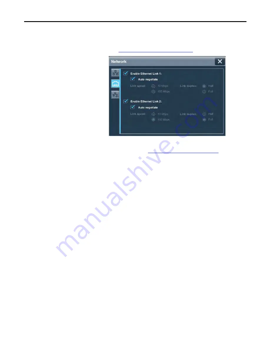
Tap the Ethernet icon.

5.

Configure the Ethernet ports for the terminal.

See 

Configure the Ethernet Ports on page 51

.

6.

Update the firmware by using the ControlFLASH™ software.

Begin the update at 

Get the Terminal Firmware on page 84

.

You can now download a View Designer application to the terminal. After the 
application is downloaded, the terminal resets then automatically launches the 
application.

Содержание 2715-15CA

Страница 1: ...ls Catalog Numbers 2715 T7CD 2715 T7CA 2715 B7CD 2715 B7CA 2715 T9WD 2715 T9WA 2715 T10CD 2715 T10CA 2715 B10CD 2715 B10CA 2715 T12WD 2715 T12WA 2715 T15CD 2715 15CA 2715 B15CD 2715 B15CA 2715 T19CD 2...

Страница 2: ...prohibited Throughout this manual when necessary we use notes to make you aware of safety considerations Labels may also be on or inside the equipment to provide specific precautions Allen Bradley Arm...

Страница 3: ...9 Required Circuit Port Parameters for USB Peripheral Devices 20 Mounting Considerations 21 Mounting Clearances 21 Panel Guidelines 22 Panel Cutout Dimensions 22 Product Dimensions 23 Prepare for Pane...

Страница 4: ...splay Terminal Diagnostics 59 Reboot the Terminal 61 Change the Date and Time 62 View General Information for the Configured Controller 63 Chapter4 MonitorandManageControlSystem Alarms Alarm Indicator...

Страница 5: ...port a Troubleshooting Profile 92 Export a Troubleshooting Log 93 Terminal Does Not Start Up 95 Terminal Restarts Intermittently 95 Touch Screen Issues 95 Display Issues 96 Ethernet Issues 96 Cannot D...

Страница 6: ...6 Rockwell Automation Publication 2715 UM001A EN P July 2015 Table of Contents Notes...

Страница 7: ...Designer application Package Contents This product is shipped with the following items PanelView 5500 terminal Mounting levers for panel installation Removable power terminal blocks AC or DC Product i...

Страница 8: ...ion 2715 TD001 Provides specifications and certifications for the PanelView 5500 terminal EtherNet IP Embedded Switch Technology Application Guide publication ENET AP005 Provides information on how to...

Страница 9: ...he PanelView 5500 terminal and the Logix platforms The Studio 5000 environment provides one point of access for both View Designer and Logix Designer applications Connection to one ControlLogix L7 or...

Страница 10: ...or input options 6 5 in touch or touch with keypad 9 in wide screen with touch 10 4 in touch or touch with keypad 12 1 in wide screen with touch 15 in touch or touch with keypad 19 in touch 2 Power AC...

Страница 11: ...6 L8 L7 R9 R10 Esc 7 9 8 4 5 6 1 2 3 0 R11 R12 R13 R14 R16 R15 1 2 3 4 4 Table 2 PanelView 5500 Terminal Keypad Item Feature Description 1 Navigation button Opens the navigation menu at the bottom of...

Страница 12: ...u can perform by using touch gestures see the View Designer help Studio 5000 Environment Use the Studio 5000 environment to create HMI applications for the PanelView 5500 terminal The Studio 5000 envi...

Страница 13: ...gner projects are stored as ACD files that can be downloaded to the controller 4 ACD file An Automation Controller Database ACD file An ACD file is a Logix Designer project file that contains the logi...

Страница 14: ...vice Level Ring Network Topology on page 35 Linear Network Topology on page 36 Star Network Topology on page 37 Catalog Number Explanation Product Selections Bulletin Input Type Display Size Display T...

Страница 15: ...No Description Quantity 1606 XLP95E DIN rail power supply 24 28V DC output voltage 95 W 1 1606 XLP100E DIN rail power supply 24 28V DC output voltage 100 W 1 2711P RSACDIN DIN rail power supply AC to...

Страница 16: ...16 Rockwell Automation Publication 2715 UM001A EN P July 2015 Chapter 1 Overview Notes...

Страница 17: ...Product Dimensions 23 Prepare for Panel Mounting 24 Mount the Terminal in a Panel 28 Remove and Replace the Power Terminal Block 31 Connect to DC Power 32 Connect to AC Power 33 Connect to a Network...

Страница 18: ...tings only when mounted in a panel or enclosure with the equivalent rating Subsequent sections of this publication may contain additional informationregarding specific enclosure type ratings that are...

Страница 19: ...tallation WARNING EXPLOSION HAZARD Do not disconnect equipment unless power has been removed or the area is known to be nonhazardous Do not disconnect connections to this equipment unless power has be...

Страница 20: ...nonincendive field wiring apparatus has not been evaluated for use in combination with another associated nonincendive field wiring apparatus Nonincendive Field Wiring Apparatus Associated Nonincendiv...

Страница 21: ...eptable Mounting Positions Mounting Clearances Plan for adequate space around the terminal inside the enclosure for ventilation and cables Consider the heat from other devices in the enclosure The amb...

Страница 22: ...against water and dust The panel surface must be flat and free of imperfections to maintain an adequate seal and NEMA UL Type or IP ratings Panel Cutout Dimensions Use the template that is shipped wit...

Страница 23: ...1 c c a b a b d d Table 12 PanelView 5500 Terminal Dimensions Terminal Size Input Type Height a mm in Width b mm in Overall Depth c mm in Mounted Depth d mm in 6 5 in Keypad and touch 179 7 05 285 11...

Страница 24: ...orient a lever vertically before inserting it into a slot This is the only way to slide the lever knob within the slot for positioning After sliding the lever to a specific notch rotate the lever tow...

Страница 25: ...osition in the same sequence as shown in Figure 5 on page 27 1 Flat Side Knobonreverse side of lever inserts into large end of slot 1 2 3 4 The edge of the bezel has alignment indentations to assist w...

Страница 26: ...lView 5500 Terminal This figure shows the lever orientation and lock sequence for a 10 4 in touch terminal Notch shows locked position 3 1 2 4 8 6 7 5 This 10 4 in touch terminal has alllevers locked...

Страница 27: ...0 4 in Touch Only 8 Levers 10 4 in Keypad and Touch 12 1 Touch Only 10 Levers 3 1 6 2 4 5 6 8 7 3 1 6 3 1 IMPORTANT The mounting lever orientations that are shown are required to maintain NEMA UL Type...

Страница 28: ...27 and rotate the non flat side of the levers toward panel b Tilt the terminal toward the panel cutout and guide upward into the cutout Make sure that the levers stay intact ATTENTION Disconnect all...

Страница 29: ...levers varies for each terminal size 4 Slide and rotate each lever to a notch that is one or two positions greater than the final lock position Start with the first lever in the sequence For example...

Страница 30: ...Carefully rotate the lever back toward panel d Lock the remaining levers to their final position 6 Inspect all levers and make sure each is in the correct locked position The notch on the outside of...

Страница 31: ...the terminal block to the connector WARNING Explosion Hazard If you connect or disconnect wiring while the power is on an electrical arc can occur This can cause an explosion in hazardous location ins...

Страница 32: ...als and on the terminal block 4 Secure the earth ground wire to the GND terminal on the terminal block The GND terminal must be connected to a low impedance earth ground 5 Apply power to the operator...

Страница 33: ...to the marked terminal on the terminal block The protective earth terminal must be connected to a low impedance earth ground 5 Apply power to the operator terminal ATTENTION Improper wiring of the po...

Страница 34: ...h RJ45 connectors The maximum cable length between the Ethernet ports and a 10 100Base T port on an Ethernet switch without repeaters or fiber is 100 m 328 ft IMPORTANT The terminal has dual Ethernet...

Страница 35: ...fault is corrected the supervisor reconfigures the network to operate as a normal ring versus a faulted ring For more information on DLR network topology see EtherNet IP Embedded Switch Technology App...

Страница 36: ...elView 5500 Terminal Connected Via Two DLR Ports Computer Connected Via a 1783 ETAP EtherNet IP Tap ControlLogix Controller with 1756 EN3TR or EN2TR Module Kinetix 350 Drive Connected Via a 1783 ETAP...

Страница 37: ...gure the terminal settings without updating the firmware the Settings menu shows an update firmware message at the bottom of the screen Computer Stratix 6000 Switch 1734 AENTR POINT I O Adapter with P...

Страница 38: ...et Network button To configure the Ethernet settings and update the firmware follow these steps 1 Boot up the terminal The Welcome dialog box displays 2 Tap Configure the Ethernet Network The Internet...

Страница 39: ...ernet ports for the terminal See Configure the Ethernet Ports on page 51 6 Update the firmware by using the ControlFLASH software Begin the update at Get the Terminal Firmware on page 84 You can now d...

Страница 40: ...40 Rockwell Automation Publication 2715 UM001A EN P July 2015 Chapter 2 Install the PanelView 5500 Terminal Notes...

Страница 41: ...45 Disable Downloads to the Terminal 57 Log Off of the Terminal 46 Change the HMI Device Name 58 Settings Menu 47 View the Firmware Revision 59 Configure the IP Address of the Terminal 48 Display Term...

Страница 42: ...reen 2 Previous and next buttons Taptheleftarrowtodisplaythepreviousscreen taptherightarrowbuttontodisplay the next screen 3 Log On Tap this button to open the Logon dialog box 4 Navigation button Tap...

Страница 43: ...in the text entry field 3 Backspace Tap this key to delete one character to the left at a time 4 Tap this key to toggle between Roman characters and alpha European characters Numeric keys are not par...

Страница 44: ...value for the graphic element 2 Min Max value The displayed minimum and maximum values you can enter for the selected field or element 3 Clear Tap the X to remove all numbers that are entered into th...

Страница 45: ...the keys 4 Tap OK 5 Tap the Password field The virtual keyboard opens 6 To enter your password with no spaces tap the keys Passwords are case sensitive 7 Tap OK 8 Tap Log on The Logon dialog box close...

Страница 46: ...est user has access to the current screen the terminal continues to display the current screen If the Guest user does not have access to the current screen the Home screen for the project is displayed...

Страница 47: ...work diagnostics 2 Display Adjust the brightness of the display Enable or disable the screen saver Configure the screen saver settings Calibrate the touch screen 3 HMI Device Enable or disable downloa...

Страница 48: ...r application through the IP address of the terminal Use DHCP to Assign an IP Address For the Terminal In a DHCP configuration the network assigns the IP address subnet mask and default gateway addres...

Страница 49: ...button Follow these guidelines to assign the IP Settings Configuration 5 Tap the IP address field The virtual keyboard opens 6 To enter the IP address use the virtual keyboard 7 Tap OK to close the vi...

Страница 50: ...ton on the terminal 2 Tap Settings or tab to the menu item and press Enter 3 Tap Network 4 Tap the Manually configure IP settings radio button Follow these guidelines to assign the DNS settings 5 Tap...

Страница 51: ...options for your network configuration Tap the Enable Ethernet Link 1 or Enable Ethernet Link 2 checkbox to add or remove the check mark The option is enabled when the box is checked To set the speed...

Страница 52: ...you can view Ethernet Link 1 and Ethernet Link 2 network connection data network status data and IP settings configuration data To view the Network Diagnostics screen follow these steps 1 Press the n...

Страница 53: ...ps 1 Press the navigation button on the terminal 2 Tap Settings or tab to the menu item and press Enter 3 Tap Display 4 Tap the Brightness field The virtual numeric keypad opens 5 Enter the value for...

Страница 54: ...aver for the display follow these steps 1 Press the navigation button on the terminal 2 Tap Settings or tab to the menu item and press Enter 3 Tap Display 4 Tap the checkbox next to Turn on Screen Sav...

Страница 55: ...n the screen To calibrate the touch screen follow these steps 1 Press the navigation button on the terminal 2 Tap Settings or tab to the menu item and press Enter 3 Tap Display 4 Tap Calibrate Touch A...

Страница 56: ...as they appear All processed targets are replaced with white targets A green circle with a check indicates a successful calibration A red circle with an X indicates a failed calibration If the calibra...

Страница 57: ...isable downloads to the terminal follow these steps 1 Press the navigation button on the terminal 2 Tap Settings or tab to the menu item and press Enter 3 Tap HMI Device 4 Tap the Allow Downloads and...

Страница 58: ...llow these steps 1 Press the navigation button on the terminal 2 Tap Settings or tab to the menu item and press Enter 3 Tap HMI Device The HMI device name field shows the current name 4 Tap the HMI de...

Страница 59: ...support 1 Press the navigation button on the terminal 2 Tap Settings or tab to the menu item and press Enter 3 Tap HMI Device View the firmware revision under Product Information 4 To close the windo...

Страница 60: ...econditionof105 110 C 221 230 F causesadelayed automatic system restart The restarts continue indefinitely until the system is cool enough toresume normal operation Last reboot Displays the dateand ti...

Страница 61: ...steps 1 Press the navigation button on the terminal 2 Tap Settings or tab to the menu item and press Enter 3 Tap HMI Device 4 Tap Reboot Terminal You are prompted to confirm the reboot 5 To reboot th...

Страница 62: ...Time 4 Change the Date and Time fields as appropriate a Tap a Date or Time field The virtual keyboard opens b Enter a value and tap OK 5 Change the time zone if desired a To move up and down the list...

Страница 63: ...roller The path does not appear if a controller is not configured for the project Controller name The name of the controller that is configured in the Logix Designer application The name does not appe...

Страница 64: ...64 Rockwell Automation Publication 2715 UM001A EN P July 2015 Chapter 3 Configure Terminal Settings Notes...

Страница 65: ...or The Unacked icon in the system banner displays the number of unacknowledged alarms for the system Tap the Unacked icon to open the alarm summary and view the system alarms Topic Page Alarm Indicato...

Страница 66: ...ealarmmanagerscreen Thealarmmanagerlistsallalarmsthatare configured in the system and their current states Therefore the alarm manager shows alarms that are not shown in the alarm summary and provides...

Страница 67: ...The reset is performed for all conditions of the currently selected alarm Reset Latched Sets the selected digital latched state of the alarm to normal if the input of the alarm has returned to normal...

Страница 68: ...larm summary to monitor and interact with alarms To view the alarm summary for the control system follow these steps 1 Press the navigation button on the terminal 2 3 Tap Alarm Summary or tab to the m...

Страница 69: ...To manage the alarms for the control system follow these steps 1 Press the navigation button on the terminal 2 3 Tap Alarm Manager or tab to the menu item and press Enter 4 Tap the alarm function keys...

Страница 70: ...l Descriptions Alarm Detail Description Acknowledge Time The time the selected alarm was acknowledged Alarm Class The user defined class that is assigned to the alarm in the Logix Designer project Ala...

Страница 71: ...me Out of Alarm Time The time the selected alarm entered the Normal or Inactive state Priority The urgency of the alarm condition Low Medium High Urgent Quality The list of reasons why thealarm is of...

Страница 72: ...m Alarms Filter the Alarms You can filter the alarms to view only the alarms in the selected alarm state To filter the alarms follow these steps 1 Tap the filter pull down arrow 2 Tap the up or down a...

Страница 73: ...A EN P July 2015 73 Monitor and Manage Control System Alarms Chapter 4 The selected filter displays in the filter pull down menu To change the filter tap the filter pull down menu and select another f...

Страница 74: ...74 Rockwell Automation Publication 2715 UM001A EN P July 2015 Chapter 4 Monitor and Manage Control System Alarms Notes...

Страница 75: ...ernal damage and affect normal operation Follow these guidelines when you handle this equipment Touch a grounded object to discharge potential static Wear an approved grounding wriststrap Do not touch...

Страница 76: ...the USB device port IMPORTANT See page 20 for information on the USB host ports and USB peripheral devices in hazardous locations IMPORTANT The USB host connections can be used with an external keybo...

Страница 77: ...steps 1 Verify that the SD card is locked or unlocked according to your preference If unlocked the terminal can write data to or read data from the card If locked the terminal can only read data from...

Страница 78: ...old or distributed in California USA 1 6 1 6 SD Slot This product contains a sealed lithium battery which may need to be replaced during the life of the product At the end of its life the battery cont...

Страница 79: ...play module and turn over to expose the circuit board 4 Locate the coin cell battery on the circuit board 5 Remove the battery by lifting on the side of the battery 6 Insert the new battery with the p...

Страница 80: ...that is removed by pulling back on a tab Do not remove the liner until you are ready to install the overlay Before installing the overlay clean the touch screen and keys if present by using a lint fre...

Страница 81: ...n the screen Make sure that the overlay lies flat with no bubbles or warps 4 With a soft cloth or finger press around the edges of the overlay to seal it and remove any air bubbles trapped in the adhe...

Страница 82: ...82 Rockwell Automation Publication 2715 UM001A EN P July 2015 Chapter 5 Install and Replace Components Notes...

Страница 83: ...the terminal Verify the catalog number of your product and the current firmware revision on the terminal See View the Firmware Revision on page 59 to get the catalog number and current firmware revisi...

Страница 84: ...ControlFLASH software is required to update firmware on the PanelView 5500 terminal This software is included in the Studio 5000 installation package For details on how to install ControlFLASH softwar...

Страница 85: ...e the ControlFLASH software to update the firmware in a PanelView 5500 terminal follow these steps 1 Click Start Programs FLASH Programming Tools ControlFLASH 2 Make sure that you know the required in...

Страница 86: ...P July 2015 Chapter 6 Update Firmware 4 Browse to and select the device to update on the EtherNet IP network and click OK 5 Select the firmware revision to install and click Next 6 Read the Danger in...

Страница 87: ...plete If the update was successful the Status area is green 8 Click OK If the update fails the status area is red and reads Update failure See the ControlFlash firmware update Kit User Manual publicat...

Страница 88: ...88 Rockwell Automation Publication 2715 UM001A EN P July 2015 Chapter 6 Update Firmware Notes...

Страница 89: ...for the Configured Controller 91 Troubleshooting Profiles 91 Terminal Does Not Start Up 95 Terminal Restarts Intermittently 95 Touch Screen Issues 95 Display Issues 96 Ethernet Issues 96 Cannot Downlo...

Страница 90: ...uring startup If the indicators remain off check the power cable After a successful startup the STS indicator remains on Table 23 shows indicator states if the terminal stops during startup Table 23 F...

Страница 91: ...at This profile is stored on the terminal and can be used to improve usability and assist with troubleshooting If you contact technical support a representative can ask you to export the troubleshooti...

Страница 92: ...mported file appears next to the Import Profile button To import a troubleshooting profile from a USB drive or SD card follow these steps 1 Press the navigation button on the terminal 2 Tap Settings o...

Страница 93: ...ockwell Automation technical support Export a Troubleshooting Log To export the troubleshooting log to a USB device or SD card follow these steps 1 Press the navigation button on the terminal 2 Tap Se...

Страница 94: ...e troubleshooting log is exported and the date a time of the last export is displayed next to the Export button 9 To close the window tap X Your technical support contact at Rockwell Automation can pr...

Страница 95: ...Verify that nothing is pressing against the display or that you are not touching the display during startup Table 25 Terminal Restarts Intermittently Check For What to Do See Improper power wiring Ver...

Страница 96: ...to consider include The possibility of an unreadable touch screen The possibility of an inoperable touch screen Unexpected communication errors or delays Operator error in the control of the system P...

Страница 97: ...ils toacquire an IPaddressfromthenetwork Ingeneral anIPaddressthatbegins with 169 does not support a network connection See Configure the IP Address of the Terminal on page 48 Conflict Between IP addr...

Страница 98: ...follow these steps 1 Rub lightly with isopropyl alcohol 70 concentration 2 To remove residue use a mild soap or detergent solution 3 Rinse with clean water Equipment Wash Downs ATTENTION Do not use ab...

Страница 99: ...tomation is not responsible for damage to a product that is shipped or transported while installed in a panel or enclosure ATTENTION Theprocessthatrestoresfactorydefaultsalsoremovessomedata Upload the...

Страница 100: ...applications 4 Tap Yes to continue or Cancel to resume a normal startup Progress messages appear on the screen during the restore operation When the restore is complete the terminal performs a normal...

Страница 101: ...r terminal blocks 15 protective overlays 15 SD cards 15 circuit breaker rating 18 ControlFLASH software 83 84 cutout dimensions 22 D date and time setting 62 DC power bus 32 connection 32 earth ground...

Страница 102: ...unt the terminal ambient temperature 21 cutout dimensions 22 minimum clearances 21 mounting positions 21 panel guidelines 22 preparation 24 mounting levers 24 mouse 11 N navigation button 11 keys 11 n...

Страница 103: ...dio 5000 Logix Designer 7 see also Logix Designer Studio 5000 View Designer 7 see also View Designer supervisor nodes 35 T tag browser 13 terminal blocks 31 time and date setting 62 topology network D...

Страница 104: ...104 Rockwell Automation Publication 2715 UM001A EN P July 2015 Index...

Страница 105: ......

Страница 106: ...t is not functioning and needs to be returned follow these procedures Documentation Feedback Your comments will help us serve your documentation needs better If you have any suggestions on how to impr...

Отзывы: