background image

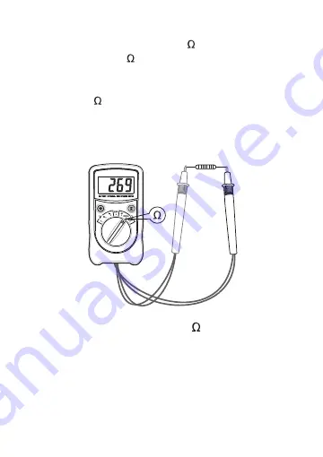
1.  Set the range switch to desired     range position.
2.  Connect the test probes across the resistor to be
     measured.
3.  Read the reading on the display.

Note:

1.  The resistance is measured by the meter with an AC
     signal so that the capacitance value and inductance

Measuring Resistance

6

2.  For measurements in the 200m  range, set the range
     switch in the 200m  range position and short the two
     test probes, the display will show a reading. This
     reading must be subtracted from all the measurements
     in the 200m  range.

Содержание EM3610

Страница 1: ...Battery Internal Resistance Meter 3610 Users Manual Read this manual thoroughly before use...

Страница 2: ...method to eliminate the impact of the resistance of the test leads on the measured value and the battery voltage can also be measured by the same connection method It is applicable for measurements o...

Страница 3: ...RE Storage Environment temperature 10 45 C relative humidity 85 Battery 9V battery 6F22 or equivalent 1 piece Low Battery Indication shown on the display Size 150 83 44mm only mainbody Weight about 31...

Страница 4: ...turn on the backlight The backlight will turns off automatically about 10 secs later 3 Function Range Switch Used to select desired function and range as well as to turn on or off the meter To preser...

Страница 5: ...ery Voltage Range Resolution Accuracy 0 1 999V 2 00V 19 99V 20 0V 50 0V 1mV 10mV 100mV 1 2 Range Resolution Accuracy 0 199 9m 200m 1999m 2 00 19 99 0 1m 1m 10m 3 5 Resistance Battery Internal Resistan...

Страница 6: ...ve terminal of the battery 3 Read the reading on the display 4 If the display shows 1 it means that the measured value exceeds the selected range and you should set the range switch to a higher range...

Страница 7: ...The resistance is measured by the meter with an AC signal so that the capacitance value and inductance Measuring Resistance 6 2 For measurements in the 200m range set the range switch in the 200m ran...

Страница 8: ...state the display will show 1 as an overrange indication 4 Before measurement disconnect all power to the circuit to be tested and discharge all capacitors thoroughly 5 For measurements in the 200m ra...

Страница 9: ...the negative terminal of the battery 3 Read the reading on the display The polarity of red test probe connection will be indicated as well NOTE 1 Do not apply a voltage higher than 50V between the tes...

Страница 10: ...d or skin and do not ground yourself 7 Do not use the meter if it is damaged or if it operates abnormally 8 To avoid damage to the meter do not apply any AC signal between the test probes BATTERY REPL...

Страница 11: ...erials which can be recycled Please do not discharge it in the garbage bin but check with your local council for recycling facilities in your area DECLARATION 1 This manual is subject to change withou...

Отзывы: