30
With the motor disconnected from the ESC for safety, power on your transmitter and plug a charged battery
into the ESC to provide power to the servos, gyro and receiver.
9.1
Set the swashplate (CCPM) servos to their neutral position by exactly centering the throttle/
collective stick. If your transmitter features a graphic display of pitch curves, it may be helpful to
select this menu to better determine the exact mid-stick position.
If your transmitter does not feature a graphic display, you can also set the low and high point pitch
curve values to 50% (so they are the same as the midpoint pitch curve value), so that no matter
where the throttle/collective stick is positioned, the servos will remain in their neutral position.
However, you must be sure to re-adjust the low and high point pitch curve values after installing the
servo arms to check for proper operation and for proper flight performance.
9.2
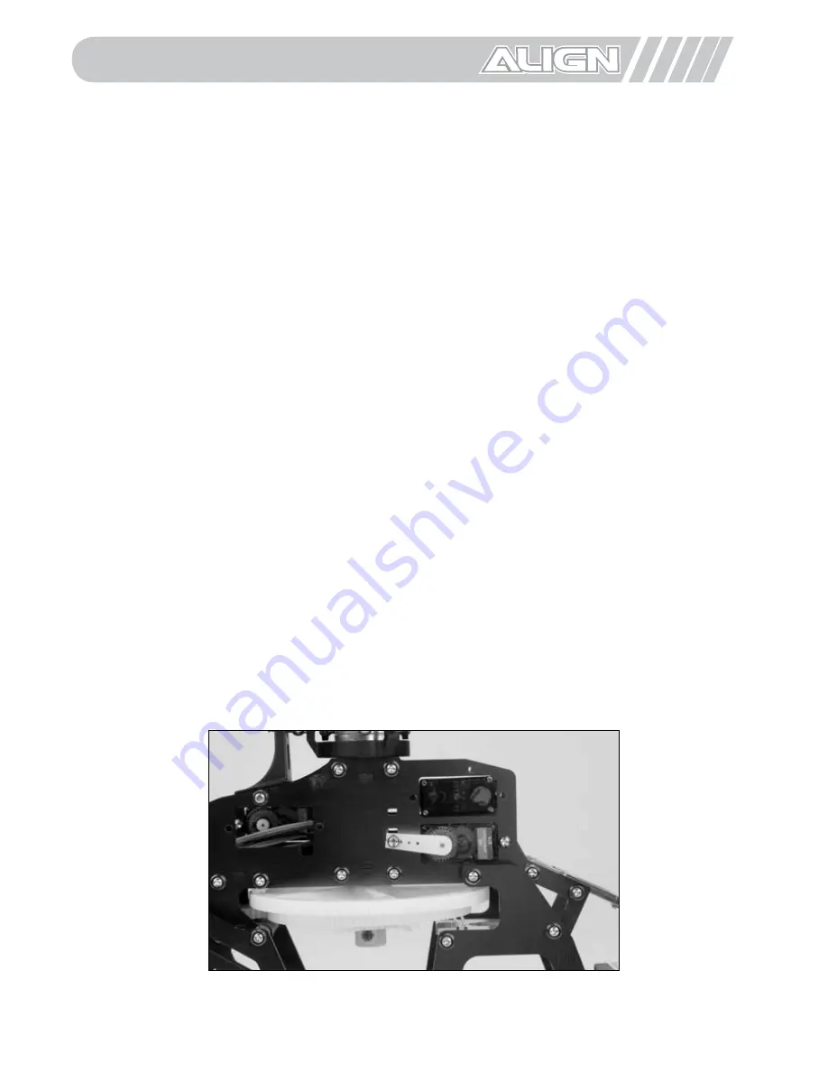
With the swashplate (CCPM) servos in their neutral position, you will need to find servo arms, that
when installed on each servo, are as close to level (horizontal) as possible.
Note, if you are using E-flite/Spektrum S75 servos, you will want to find servo arms that
are angled approximately 5–10° upward when installed with the servos in their neutral
position. This is to help prevent the servo arm from contacting the main drive gear with
a negative collective and right aileron/down elevator control input.
Don’t worry if you are not able to find an arm and/or arm position that is exactly level (or 5–10°
upward on S75 servos) as you can use sub-trim later on to set the exact position. However, be sure
to test multiple arms and arm positions (for example, if it is a two-sided arm, try both sides) on
each servo to find an arm that matches the intended position closest. This will help to minimize the
amount of sub-trim required for each servo later on.
Please see the following photos and notes to help you select the correct servo arms for your chosen
servos, and the location in which the control ball should be placed. The control balls, mounting
screws and nuts can be found in the Linkage Parts Bag. Be sure to use a small amount of R48
threadlock when installing the mounting screws and nuts, and to enlarge the mounting holes using
a sharp hobby knife or 1/16” drill bit (if required). Also, be sure to remove any unused portions of the
servo arms to prevent binding:
For E-flite/Spektrum S75 Servos
Use the “extra long/3D” two-sided arm with the control ball placed in the mounting hole 14.5mm
from the center.
9.0 Servo Arm Setup and Installation
Содержание T-REX 450SA ARF
Страница 70: ...70 Building Notes ...
Страница 71: ...71 Flying Notes ...


