Alien MAX316 Скачать руководство пользователя страница 38

ALIEN MEGA/MAX USER MANUAL 


38 


Icon 

Explanation 

Icon 

Explanation 


Edit basic parameters of the camera 


Add the detected IP camera. 


The  camera  is  connected;  you  can 

click the icon to get the live view of 

the camera. 


The camera is disconnected; you can 

click  the  icon  to  get  the  exception 

information of camera. 


Delete the IP camera 


Advanced settings of the camera


Update the IP camera 


3.


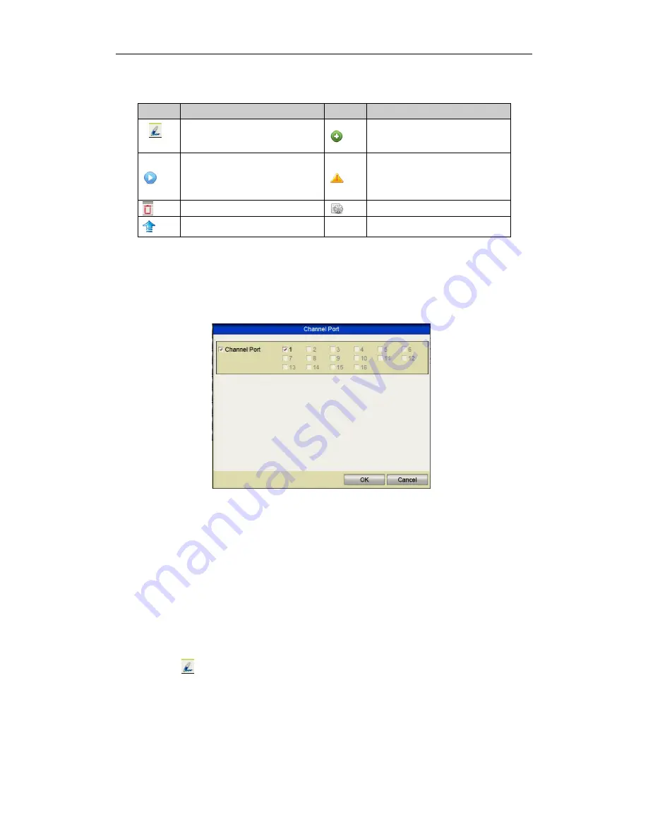
  (For the encoders with multiple channels only) check the  checkbox of Channel 

No.  in  the  display  window,  as  shown  in  the  following  figure,  and  click 

OK

  to 

finish adding. 


Figure 2.3.1.6    Selecting Multiple Channels 


2.3.2


Editing the Connected IP Cameras and Configuring


Customised 

Protocols


After the adding of the IP cameras, the basic information about the camera can be 
configured. These are listed on the configuration settings page.     

Steps: 

1.


Click 

the      icon to  edit  the parameters;  you can edit the  IP address, 

protocol and other parameters. 


Содержание MAX316

Страница 1: ...ALIEN MEGA MAX USER MANUAL 1 ALIEN Digital Video Recorders Models MEGA204 MEGA208 MEGA216 MAX316 MAX416 Version 007 Last Revised 17 6 2015...

Страница 2: ...onmental conditions meet factory specifications Use the DVR in conjunction with an UPS if possible Power down the unit before connecting and disconnecting accessories and peripherals This symbol on th...

Страница 3: ...ded allowing adjustment of interval time Quick setting menu is provided for live view The selected live view channel can be coverted Motion detection video tampering detection video exception alarm vi...

Страница 4: ...ck to go through less effective information Zooming in for any area when playback Reverse playback of multi channel Supports pause fast forward slow forward skip forward and skip backward when playbac...

Страница 5: ...ress load balance and network fault tolerance IPv6 is supported TCP IP protocol PPPoE DHCP DNS DDNS NTP SMTP UPnP and HTTPS are supported TCP UDP and RTP for unicast Auto Manual port mapping by UPnPTM...

Страница 6: ...Using the Wizard for Basic Configuration 31 2 3 Adding and Connecting the IP Cameras 35 2 3 1 Adding the Online IP Cameras 35 2 3 2 Editing the Connected IP Cameras and Configuring Customised Protoco...

Страница 7: ...9 6 1 1 Playing Back by Channel 79 6 1 2 Playing Back by Time 81 6 1 3 Playing Back by Event Search 82 6 1 4 Playing Back by Tag 84 6 1 5 Playing Back by Instant Detective Search 87 6 1 6 Playing Back...

Страница 8: ...9 4 4 Checking Network Statistics 134 9 5 Networking your DVR 135 Chapter 10 HDD Management 141 10 1 Initialising HDDs 141 10 2 Managing Network HDD 142 10 3 Managing eSATA 144 10 4 Managing HDD Group...

Страница 9: ...figuring More Settings 164 12 5 Managing User Accounts 165 12 5 1 Adding a User 165 12 5 2 Deleting a User 167 12 5 3 Editing a User 168 Chapter 13 Glossary 170 Chapter 14 Troubleshooting 171 Chapter...

Страница 10: ...menu interface 2 ABC F1 Enter numeral 2 Enter letters ABC The F1 button when used in a list field will select all items in the list In PTZ Control mode it will turn on off PTZ light and when the imag...

Страница 11: ...erent fields and items in menus In the Playback mode the Up and Down button is used to speed up and slow down recorded video The Left and Right button will select the next and previous record files In...

Страница 12: ...MENU Enter numeral 1 Access the main menu interface 2 ABC F1 Enter numeral 2 Enter letters ABC The F1 button when used in a list field will select all items in the list In PTZ Control mode it will tu...

Страница 13: ...vigate between different fields and items in menus In the Playback mode the Up and Down button is used to speed up and slow down recorded video The Left and Right button will select the next and previ...

Страница 14: ...MENU Enter numeral 1 Access the main menu interface 2 ABC F1 Enter numeral 2 Enter letters ABC The F1 button when used in a list field will select all items in the list In PTZ Control mode it will tu...

Страница 15: ...vigate between different fields and items in menus In the Playback mode the Up and Down button is used to speed up and slow down recorded video The Left and Right button will select the next and previ...

Страница 16: ...as well b when the DVR is controlled by IR remote control with the address from 1 254 and the SHIFT button is used ALARM Alarm indicator turns red when a sensor alarm is detected HDD HDD indicator bli...

Страница 17: ...TION buttons are used to navigate between different fields and items in menus In the Playback mode the Up and Down button is used to speed up and slow down recorded video The Left and Right button wil...

Страница 18: ...MAX USER MANUAL 18 No Name Function Description 7 USB Interface Universal Serial Bus USB ports for additional devices such as USB mouse and USB Hard Disk Drive HDD 8 IR Receiver Receiver for IR remot...

Страница 19: ...or does not light when the device is disarmed The arm disarm state can be initiated by pressing and holding on the ESC button for more than 3 seconds in live view mode 2 Alphanumeric Buttons Switch to...

Страница 20: ...ual Record setting menu In PTZ control settings press the button and then you can call a PTZ preset by pressing Numeric button It is also used to turn audio on off in the Playback mode PLAY AUTO Enter...

Страница 21: ...MENU WIPER button will start wiper if applicable In Playback mode it is used to show hide the control interface PREV FOCUS Switch between single screen and multi screen mode In PTZ Control mode it is...

Страница 22: ...ALIEN MEGA MAX USER MANUAL 22 1 2 IR Remote Control Operations The DVR may also be controlled with the included IR remote control Batteries 2 AAA must be installed before operation...

Страница 23: ...Button Same as the F1 LIGHT button on front panel 17 PTZ Control Buttons Buttons to adjust the iris focus and zoom of a PTZ camera 18 F2 Button Same as the F2 AUX button on front panel Troubleshooting...

Страница 24: ...ry another mouse The operation of the mouse Name Action Description Left Click Single Click Live view Select channel and show the quick set menu Menu Select and enter Double Click Live view Switch bet...

Страница 25: ...5 1 4 Input Method Description Figure 1 4 1 Soft Keyboard Description of the buttons on the soft keyboard Icons Description Icons Description English Capital English Numbers Symbols Lowercase Uppercas...

Страница 26: ...l video output and menu 5 HDMI HDMI video output connector 6 USB Port Universal Serial Bus USB port for additional devices 7 Network Interface Connector for network 8 RS 485 Interface Connector for RS...

Страница 27: ...tput Display local video output and menu 7 AUDIO OUT RCA connector 8 Network Interface Connector for network 9 RS 485 Interface Connector for RS 485 devices T and T pins connect to R and R pins of PTZ...

Страница 28: ...tput Display local video output and menu 7 AUDIO OUT RCA connector 8 Network Interface Connector for network 9 RS 485 Interface Connector for RS 485 devices T and T pins connect to R and R pins of PTZ...

Страница 29: ...ck the power supply is plugged into an electrical outlet It is HIGHLY recommended that an Uninterruptible Power Supply UPS be used in conjunction with the device 2 Turn on the power switch on the rear...

Страница 30: ...e front panel for MAX316 and MAX416 1 Press and hold the POWER button on the front panel for 3 seconds 2 Enter the administrator s username and password in the dialogue box for authentication 3 Click...

Страница 31: ...you run through the setup If initiated the Setup Wizard will start once the DVR has loaded as shown below Steps 1 Please select the resolution of the monitor in the drop down list Figure 2 2 1 Resolut...

Страница 32: ...e DVR Failure to do this could allow access to your DVR from malware that may leave the unit unusable 5 To change the admin password click the New Admin Password checkbox Enter the new password and co...

Страница 33: ...ith three working modes configurable multi address load balance network fault tolerance options 4 Click Next button after you having configured the network parameters which will take you to the Advanc...

Страница 34: ...isation will remove all the data saved in the HDD 8 Click Next button to enter the IP Figure 2 2 8 IP Settings 9 Click Next button to enter the Record Settings window Figure 2 2 9 Record Settings 10 C...

Страница 35: ...n is valid and correct For detailed checking and configuring of the network please see Chapter 9 Network Settings Please refer to the individual DVR specifications for number of connectable network ca...

Страница 36: ...P cameras Icon Explanation Icon Explanation Edit basic parameters of the camera Add the detected IP camera The camera is connected The camera is disconnected you can click the icon to get the exceptio...

Страница 37: ...her information of the IP camera to be added 3 Click Add to add the camera OPTION 2 Steps 1 Enter the Camera Management interface Menu Video Camera IP Camera Figure 2 3 1 4 Main Menu 2 Repeat step 3 a...

Страница 38: ...Update the IP camera 3 For the encoders with multiple channels only check the checkbox of Channel No in the display window as shown in the following figure and click OK to finish adding Figure 2 3 1...

Страница 39: ...the dropdown list 2 Click OK to save the settings and exit the editing interface To edit advanced parameters 1 Drag the horizontal scroll bar to the right side and click the icon Figure 2 3 2 2 Networ...

Страница 40: ...In live view mode there are many functions provided The functions are listed below Single Screen show only one channel on the monitor Multi screen show multiple channels on the monitor simultaneously...

Страница 41: ...on Previous screen left direction button Auto switch Press Enter button Playback Press Play button 3 2 2 Using the Mouse in Live View Name Description Menu Enter the main menu of the system by right c...

Страница 42: ...tput with the F1 button on front panel or VOIP MON button on IR remote control and then press the Enter button MEGA204 208 216 MAX316 MAX416 Figure 3 2 1 1 Right click Menu 3 2 3 Main Aux Output Switc...

Страница 43: ...Quick Setting Toolbar in Live View Mode On the screen of each channel there is a quick setting toolbar which shows when you point the mouse at the bottom of the screen Figure 3 2 41 Quick Setting Tool...

Страница 44: ...t the image is smoother than the other two modes Outdoor the image is relatively clearer and sharper The degree of contrast and saturation is high Figure 3 2 4 3 Image Settings You can adjust the imag...

Страница 45: ...el display and by clicking on one of the imbedded channels a full channel screen display for that channel is displayed Steps 1 Enter the Live View Settings interface Menu Setup Live View 2 Select the...

Страница 46: ...he MEGA204 MEGA208 and MEGA216 provide HDMI VGA outputs and MAX316 and MAX416 models provide HDMI VGA and CVBS outputs for selection Live View Mode Designates the display mode to be used for Live View...

Страница 47: ...ouble click a camera name in the camera list you would like to display Setting an X means the window will not display any camera 3 You can also click to start live view of all channels in order and cl...

Страница 48: ...Video Manual Video Quality Diagnostics Figure 3 5 1 Video Quality Diagnostics 2 Check the checkboxes to select the channels for diagnostics 3 Click the button Diagnose and the results will be display...

Страница 49: ...ose After logging out the monitor returns to the live view mode and if you want to do some operations you need to enter user name and password to log in again Steps 1 Enter the Shutdown menu Menu Turn...

Страница 50: ...ters for PTZ The configuring of the PTZ parameters must be done for you control the PTZ camera Steps 1 Enter the PTZ Settings interface Menu Video PTZ Figure 4 1 1 PTZ Settings 2 Choose the camera for...

Страница 51: ...mera to point to when an event takes place Steps 1 Enter the PTZ Control interface Menu Video PTZ Figure 4 2 1 1 PTZ Settings 2 Use the direction buttons to move the camera to the location where you w...

Страница 52: ...e corresponding text field 5 Click the Call Preset button to call it Figure 4 2 2 5 PTZ Panel General 4 2 3 Customising Patrols General The DVR uses a standardised method of controlling Tours Patrols...

Страница 53: ...at the corresponding key point The Speed defines the speed at which the PTZ will move from one key point to the next 5 Click the Add button to add the next key point to the patrol or you can click the...

Страница 54: ...4 2 4 2 PTZ Panel General 3 Select a patrol in the dropdown list and click the Call Patrol button to call it 4 You can click the Stop Patrol button to stop calling it Note that most PTZ cameras trigge...

Страница 55: ...terface or press the PTZ button on the front panel or click the PTZ Control icon in the quick setting bar or select the PTZ option in the right click menu to show the PTZ control panel 2 Click the but...

Страница 56: ...e Follow the procedure to call the Auto Scan Steps 1 Click the button PTZ in the lower right corner of the PTZ setting interface or press the PTZ button on the front panel or click the PTZ Control ico...

Страница 57: ...e one touch function of the PTZ control Figure 4 2 9 1 PTZ Panel One touch 3 There are 3 one touch park types selectable click the corresponding button to activate the park action Park Quick Patrol Th...

Страница 58: ...interface In PTZ control mode the PTZ panel will be displayed when a mouse is connected with the device If no mouse is connected the PTZ icon appears in the lower left corner of the window indicating...

Страница 59: ...l 2 Click Advance to check the storage mode of the HDD 1 Whether the HDD mode is Quota please set the maximum record capacity For detailed information see Chapter 0 Configuring Quota Mode 2 If the HDD...

Страница 60: ...for a recorded file to be kept on the HDD If the deadline is reached the file will be deleted You can set the expired time to 0 and then the file will not be deleted The actual keeping time for the fi...

Страница 61: ...igure the parameters 4 Click Apply to save the settings 5 Optional If the parameters can also be used to other cameras click Copy to copy the settings to other channels You can only copy the same sett...

Страница 62: ...he camera will automatically start stop recording according to the configured schedule Steps 1 Enter the Record Schedule interface Menu Schedule Schedule MEGA DVR Range Figure 5 2 1 Record Schedule 2...

Страница 63: ...edules leave the All Day checkbox blank and set the Start End time Figure 5 2 3 Edit Schedule Set Time Period Up to 8 periods can be configured for each day The time periods cannot overlap each other...

Страница 64: ...nterface explains each record option Figure 5 2 5 Draw the Schedule Description of the colour icons are shown below Figure 5 2 6 Descriptions of the Color Icons 2 Click and drag the mouse on the sched...

Страница 65: ...warning notify a surveillance center and send emails etc Steps 1 Enter the Motion Detection interface Menu Video Motion Figure 5 3 1 Motion Detection 2 Configure Motion Detection 1 Choose the camera...

Страница 66: ...which you want the motion detection event to trigger recording 7 Click Apply to save the settings 8 Click OK to back to the upper level menu 9 Exit the Motion Detection menu 3 Configuring the schedule...

Страница 67: ...Alarm Settings 2 Click the Alarm Input tab Figure 5 4 2 Alarm Settings Alarm Input 1 Select Alarm Input number and configure alarm parameters 2 Choose N O normally open or N C normally closed for alar...

Страница 68: ...figure other alarm input parameters If the setting can also be applied to other alarm inputs click Copy and choose the alarm input number Figure 5 4 4 Copy Alarm Input 3 Configure the schedule Please...

Страница 69: ...ter the VCA settings interface and select a camera for the VCA settings Menu Video VCA Figure 5 5 1 VCA Settings 2 Configure the detection rules for VCA events For details see Chapter 8 Detecting VCA...

Страница 70: ...TZ Linking function is only available for the VCA settings of IP cameras 4 Enter Record Schedule settings interface Menu Schedule Schedule Record and then set VCA as the record type For details see Ch...

Страница 71: ...unning 24 x 7 When the DVR is rebooted the manual settings are cancelled Steps 1 Enter the Manual settings interface Menu Instant Figure 5 6 1 Manual Record 2 Enable manual record 3 Click the Analogue...

Страница 72: ...Figure 5 7 1 Holiday Settings 3 Enable Edit Holiday schedule 1 Click to enter the Edit interface Figure 5 7 2 Edit Holiday Settings 2 Click the Enable checkbox 3 Select Mode from the dropdown list The...

Страница 73: ...re 5 7 3 Edit Schedule Holiday Up to 8 periods can be configured for each day The time periods must not overlap In the schedule time table both the holiday schedule and the normal day schedule are dis...

Страница 74: ...undant For detailed information please refer to Chapter 9 8 Managing HDD Group There should be at least another HDD which is in Read Write status Steps 1 Enter HDD Information interface Menu Drives Ge...

Страница 75: ...meters 2 Select Camera you want to configure 3 Click on the Redundant Record checkbox 4 Click Apply to save settings If the encoding parameters are required to be applied to other cameras click Copy a...

Страница 76: ...terface 4 Configuring HDD group 1 Choose a group number for the HDD group Figure 5 9 1 Drives General 2 Click Apply to save your settings 3 Click OK to return to previous menu Repeat the above steps t...

Страница 77: ...Configure the record type file type start time and end time 4 Click Search to show the results Figure 5 10 2 Export Search Result 5 Protect the recorded files 1 Find the recorded file s you want to pr...

Страница 78: ...Figure 5 10 4 Drives General Editing 3 Set the HDD to Read only 4 Click OK to save settings and return to previous menu You cannot save any files to an HDD if in Read only mode If you want to save fil...

Страница 79: ...s supported OPTION 1 Choose a channel in live view mode using the mouse and click the play button in the quick setting toolbar Play Button Only record files recorded during the last five minutes on th...

Страница 80: ...hannel in single screen live view mode In multi screen live view mode the recorded files of the top left channel will be played back For the MAX316 and MEG416 pressing numerical buttons will switch pl...

Страница 81: ...t day Full Screen Speed Up Speed Down Exit Process bar Video type bar Blue Normal Red Event Recording Time Bar Zoom In Time Bar Zoom Out indicates the start time end time of the record files represent...

Страница 82: ...r 2 Click and select to enter the Event Playback interface 3 Select Alarm Input Motion Line Figure 6 1 3 2 Playback Options Crossing Detection Intrusion Detection as the event type and specify the sta...

Страница 83: ...ent Pre play and post play can be configured for the playback of event triggered record files Pre play The time you set to play back before the event For example when an alarm triggers a recording at...

Страница 84: ...bar use the mouse to click any point on the progress bar or drag the progress bar to locate special frames About video type bar represents normal recording manual or schedule represents event recordi...

Страница 85: ...to a single video file 3 Tag management Click button to check edit and delete tag s Figure 6 1 4 2 Tag Management Interface Steps 1 Select the Tag from the drop down list in the Playback interface 2...

Страница 86: ...3 Video Search by Tag 3 Click button to play back the file You can click the Back button to return to the search interface Pre play and post play can be configured Figure 6 1 4 4 Playback by Tag Inter...

Страница 87: ...1 5 Playing Back by Instant Detective Purpose The Instant Detective playback function provides an easy way to get through the less effective information When you select the Instant Detective playback...

Страница 88: ...the detection area 5 Click the to search and then the result will be displayed as on the progress bar in the Instant Detective Playback interface Alternatively you can click the button to clear all t...

Страница 89: ...ols Log Information Figure 6 1 6 1 System Log Search Interface 2 Click Log Search tab to enter Playback by System Logs Set search time and type then click Search button Figure 6 1 6 2 Result of System...

Страница 90: ...o look up and play back files on external devices Note that playback will only work with this DVR s supported camera formats Steps 1 Enter the Playback Search interface Menu Playback 2 Select the Exte...

Страница 91: ...e frame It is also feasible to use the pause button in toolbar Using the front panel Some DVRs will not support this function Press the button to set the speed to Single frame One click on the playbac...

Страница 92: ...mode Up to 16 ch with 1920 1080 resolution simultaneous reverse playback is supported Steps 1 Enter Playback interface Menu Playback 2 Check more than one checkbox to select multiple channels and clic...

Страница 93: ...ives USB HDDs and USB writer Steps 1 Enter Export interface Menu Backup Normal Figure 7 1 1 1 Normal Export Interface 2 Set search condition and click Search button to enter the search result interfac...

Страница 94: ...cking the Format button Figure 7 1 1 3 Export by Normal Video Search using USB Flash Drive Figure 7 1 1 4 Export by Normal Video Search using USB Writer Stay in the Exporting interface until all recor...

Страница 95: ...erface Menu Backup Normal Set search condition and click Search button to enter the search result interface 3 Select record files you want to back up Click button to play the recorded file if you want...

Страница 96: ...be exported automatically during the export if selected Figure 7 1 1 7 Checkup of Export Result Using eSATA HDD 7 1 2 Backing up by Event Search Purpose Back up event related recording files using US...

Страница 97: ...d click Quick Export button to enter Export interface 2 Clicking Details button will take you to the interface with detailed information of all channels triggered by the event Figure 7 1 2 2 Result of...

Страница 98: ...u can also format USB flash drive or USB HDDs via the device Figure 7 1 2 4 Export by Event Using USB Drive Stay in the Exporting interface until all record files are exported with display message Exp...

Страница 99: ...as USB flash drives USB HDDs and USB writers Steps 1 Enter Playback interface Please refer to Chapter 6 Playback Figure 7 1 3 1 Interface of Playback 2 During playback use buttons and in the playback...

Страница 100: ...lash Drive Stay in the Exporting interface until all recorded files have been exported with Export finished message displayed 5 If there are clips not saved a prompt will display when you quit the Pla...

Страница 101: ...Search Result interface At least one channel must be selected Figure 7 2 1 Normal Video Search for Backup 2 Select the recorded files you want to backup At least one file must be selected Figure 7 2 2...

Страница 102: ...ss button to play it Click Format button to format the backup device If the inserted USB device is not recognised Click the Refresh button Reconnect device Check for compatibility from vendor Manageme...

Страница 103: ...eps 1 Enter Motion Detection interface in Camera Management and choose a camera you want to set up for motion detection Menu Video Motion Figure 8 1 1 Motion Detection Setup Interface 2 Set detection...

Страница 104: ...e Copy button to copy the time period settings to other day s Time periods must not be duplicated or overlap Figure 8 1 4 Set Arming Schedule of Motion Detection 5 Click Linkage Action tab to set up a...

Страница 105: ...Status Interface 2 Set the handling method of the selected alarm input Click the Enable checkbox and button to set alarm response actions Figure 8 2 2 Alarm Input Settings Interface 3 Select Trigger C...

Страница 106: ...chedule to other days 6 If necessary select PTZ Linking tab and set PTZ linkage for the alarm input Set PTZ linking parameters and click the OK button to complete the alarm input settings Please check...

Страница 107: ...gure 8 3 1 Video Loss Setup Interface 2 Set up handling method for video loss Click the checkbox Enable Video Loss Alarm Click Settings button to set up handling method of video loss 3 Set arming sche...

Страница 108: ...sponse Actions later in this chapter 5 Click the OK button to complete the video loss settings for the channel Repeat the above steps to finish settings of other channels or click the Copy button to c...

Страница 109: ...t not be duplicated or overlap Figure 8 4 2 Set Arming Schedule for Video Tampering 3 Select Linkage Action tab to set alarm response actions for video tampering alarm please refer to Setting Alarm Re...

Страница 110: ...gue camera channel for VCA but 2 analogue camera channels for the MAX416 Steps 1 Enter VCA Alarm interface in Camera Management and select a camera you want to detect the VCA alarm Menu Video VCA REMI...

Страница 111: ...he Enable checkbox to enable the selected VCA detection 5 Click the Settings to configure the trigger channel arming schedule and linkage actions Figure 8 5 2 Set Triggering Channel for VCA Alarm 1 Se...

Страница 112: ...later in this chapter 4 Click the OK button to complete the VCA alarm settings for the channel 6 Configure the region and other settings for the selected VCA detection Task1 Configure the Line Crossin...

Страница 113: ...he full screen in the preview window for the selected intrusion region You can use the to clear the existing region and re draw it 6 Repeat the above steps to set other intrusion regions 7 Click Apply...

Страница 114: ...p Figure 8 6 1 Set Arming Schedule for Video Quality Diagnostics 3 Select Linkage Action tab to set alarm response actions for video tampering alarm please refer to Setting Alarm Response Actions late...

Страница 115: ...Exception No space for saving recorded files Steps 1 Enter Exceptions interface and handle various exceptions Menu Setup Exceptions Figure 8 7 1 Exception Settings Interface 2 Click the checkbox of E...

Страница 116: ...k to the Live View interface Audible Warning Trigger an audible beep when an alarm is detected Notify Surveillance Center Sends an exception or alarm signal to a remote alarm host when an event occurs...

Страница 117: ...plete the arming schedule setting 4 Click the Apply button to save the settings 8 9 Triggering or Clearing Alarm Output Manually Purpose Sensor alarms can be triggered or cleared manually If Manually...

Страница 118: ...ALIEN MEGA MAX USER MANUAL 118 Figure 8 9 1 Clear or Trigger Alarm Output Manually...

Страница 119: ...d for MEGA204 MEGA208 MEGA216 AND MAX316 Two self adaptive 10M 100M 1000M network interfaces are available on the MAX416 which provide three configurable working modes multi address load balance and n...

Страница 120: ...s a default route When the system is connecting via an extranet the data will be forwarded through the default route Net fault Tolerance Mode This mode allows two NIC cards to use the same IP address...

Страница 121: ...4 If you are using the AlienDDNS service then all you need to do is to enter a valid Email address in the box right of Email and press Apply then wait When you click in the blank Email box you will se...

Страница 122: ...ptional alternatives 5 Select alternative DDNS Type Four additional DDNS types are selectable IPServer DynDNS PeanutHull or NO IP IPServer Enter Server Address for IPServer Figure 9 2 1 2 IPServer Set...

Страница 123: ...not generally used in the UK and is aimed at the American market Steps 1 Enter the Network Settings interface Menu Configuration Network 2 Select the PPPoE tab to enter the PPPoE Settings interface F...

Страница 124: ...erver IP address of NTP server NTP Port Port of NTP server 5 Click the Apply button to save and exit the interface The time interval can be set from 1 to 10080 minutes and the default value is 60 minu...

Страница 125: ...as the Alien Viewer will do this automatically 9 2 5 Configuring NAT UPnP Purpose Universal Plug and Play UPnP can permit automatic port forwarding on a router Before you start If you want to use the...

Страница 126: ...s 1 Click to activate the External Port Settings dialogue box Configure the external port No for server port http port and RTSP port respectively You can use the default port number or change it accor...

Страница 127: ...ered This option is currently under development Alarm Host IP refers to the IP address of the remote PC on which the Client software is installed and the Alarm Host Port must be the same as the alarm...

Страница 128: ...ck the Apply button to save and exit the interface 9 2 7 Configuring HTTPS Port Purpose HTTPS provides authentication of the web site and associated web server that one is communicating with which pro...

Страница 129: ...rmation 3 Click OK to save the settings OPTION 2 Create the authorised certificate 1 Click the Create button to create the certificate request 2 Download the certificate request and submit it to the t...

Страница 130: ...y the Preferred DNS server must be configured Before you start Make sure you have configured the IPv4 Address IPv4 Subnet Mask IPv4 Gateway and the Preferred DNS Server in the Network Settings menu Pl...

Страница 131: ...l refers to the time between two actions of sending attached pictures E mail Test Sends a test message to verify that the SMTP server can be reached 4 Click the Apply button to save the Email settings...

Страница 132: ...rough the network detection function including network delay packet loss etc 9 4 1 Testing Network Delay and Packet Loss Steps 1 Enter the Network Traffic interface Menu Tools Net Detect 2 Click the N...

Страница 133: ...al backup device cannot be displayed If it fails to detect the backup device please check whether it is compatible with the DVR You can format the backup device if the format is incorrect Figure 9 4 2...

Страница 134: ...Configuration 9 4 4 Checking Network Statistics Purpose You can check the network statistics to obtain the device real time information Steps 1 Enter the Network Statistics interface Menu Tools Net De...

Страница 135: ...ct a LAN or patch cable from DVR to router NOT THE YELLOW CROSSOVER CABLE 3 In the DVR menu select Setup then Network and tick Enable DHCP box Press Apply and then Back 4 Click on Tools and Network on...

Страница 136: ...ll now be displayed with a flashing cursor 16 Type ping space IPv4 Address supplied by DHCP in step 4 and Enter 17 Check packets sent packets received and packets lost at bottom of reply 18 If not 4 p...

Страница 137: ...vice 20 Enter the Network Settings interface Menu Setup Network Change the Preferred DNS Server to the same address as the IPv4 Default Gateway Change the Alternate DNS Server to 8 8 8 8 Now click app...

Страница 138: ...assistance 23 To check if the dynamic system is working then instead of using an IP address and port use the dynamic name and the port If ports are closed but open when trying the current public addre...

Страница 139: ...DDNS service the dynamic name dvr serial no ippostcode com must be entered in CCTVWindow This is explained below 37 Launch CCTVWindow 38 Enter user admin password 666666 39 Click on Setup 40 In left h...

Страница 140: ...VR Ensure username and password is the same as that used to access the DVR menu User is admin and Password by default is 555555 Port number is 8240 Remote Connection 50 Add a device calling it somethi...

Страница 141: ...es General Figure 10 1 1 HDD Information Interface 2 Select HDD to be formatted 3 Click the Format button Figure 10 1 2 Confirm Initialisation 4 Select the OK button to start initialisation Figure 10...

Страница 142: ...efault and the HDDs that are not in continuous use will be place in sleeping mode Unclick the checkbox for Enable HDD Sleeping and the HDDs will work continuously 10 2 Managing Network HDD Purpose You...

Страница 143: ...disk from the list shown below You can manually enter the directory in the text field of NetHDD Directory 4 Click OK to add the configured NAS disk Up to 8 NAS disks can be added Figure 10 2 3 Add NAS...

Страница 144: ...n there is an external eSATA device connected to the DVR you can configure eSATA for Recording Record or Backup Export and you can manage the eSATA in the DVR Steps 1 Enter the Advanced Record Setting...

Страница 145: ...HDD Groups Purpose Multiple HDDs can be managed in groups Video from specified channels can be recorded onto a particular HDD group through HDD settings Steps 1 Enter the Storage Mode interface Menu D...

Страница 146: ...efore setting the HDD property please set the storage mode to Group refer to step1 4 of Chapter 10 4 Setting HDD Groups An HDD can be set to read only to prevent important recorded files from being ov...

Страница 147: ...figuring Quota Mode Purpose Each camera can be configured with allocated quota for the storage of recorded files Steps 1 Enter the Storage Mode interface Menu Drives Advanced 2 Set the Mode to Quota T...

Страница 148: ...ill use the total capacity of HDD for recording 10 5 Checking HDD Status Purpose You may check the status of the installed HDDs on DVR so as to take immediate check and maintenance in case of HDD fail...

Страница 149: ...ng Analysis and Reporting Technology is a monitoring system for HDD to detect and report on various indicators of reliability in the hopes of anticipating failures Steps 1 Enter the HDD Detect interfa...

Страница 150: ...Figure 10 7 1 SMART Test 2 Click the Bad Sector Detection tab to enter the interface 3 Select a HDD and click the Detect button to start detecting Figure 10 7 2 Bad Sector Detecting 4 You can click th...

Страница 151: ...nce Center Send Email and Trigger Alarm Output Please refer to Chapter 8 8 Setting Alarm Response Actions Figure 10 8 1 Configure HDD Error Alarm 4 When the Trigger Alarm Output is selected you can al...

Страница 152: ...red and the size of each area can be adjusted 5 The configured privacy mask zones on the window can be cleared by clicking the corresponding Clear Zone1 4 icons on the right side of the window or clic...

Страница 153: ...period and associate this time with brightness contrast saturation etc The time periods cannot overlap each other 4 Select the mode from the drop down list of Modes which are Standard Indoor Dim Light...

Страница 154: ...he Camera Name in the text field 4 Configure the Display Name Display Date and Display Week by checking the checkbox 5 Select the Date Format Time Format Display Mode and the OSD font Figure 10 11 1 O...

Страница 155: ...ras 2 Select the camera s to be configured with the same OSD settings You can also click the checkbox Analog to select all cameras 3 Click the OK button to finish the Copy settings and return to the O...

Страница 156: ...system information of the device Figure 11 1 1 System Information Interface 11 2 Searching and Exporting Log Files Purpose The operation alarm exception and information of the DVR can be stored in log...

Страница 157: ...g files can be displayed each time Figure 11 2 2 Log Search Results 5 You can click the button for each log or double click it to view its detailed information as shown below You can also click the bu...

Страница 158: ...Info Purpose The setup information regarding an IP camera can copied into an Excel file and exported to a local backup device including the IP address port admin password etc The exported file can be...

Страница 159: ...ers Steps 1 Enter the Import Export Configuration File interface Menu Tools Import Export Figure 11 4 1 Import Export Config File 2 Click the Export button to export configuration files to the selecte...

Страница 160: ...e Local Upgrade tab to enter the local upgrade menu Figure 11 5 1 1 Local Upgrade Interface 4 Select the update file from the backup device 5 Click the Upgrade button to start upgrading 6 After the up...

Страница 161: ...6 Restoring Default Settings Steps 1 Enter the Default interface Menu Tools Default Figure 11 6 1 Restore Factory Default 2 Click the OK button to restore the default settings Except the network param...

Страница 162: ...rt Transparent Channel Connect a serial device directly to the device The serial device will be controlled remotely by the PC through the network Steps 1 Enter the RS 232 Settings interface Menu Setup...

Страница 163: ...t Select the date format System Date Select the system date System Time Select the system time Mouse Pointer Speed Set the speed of mouse pointer 4 levels are configurable Enable Wizard Enable disable...

Страница 164: ...S Output Brightness Adjust the video output brightness via the CVBS interface The MEGA204 MEGA208 and MEGA216 provide no CVBS output Auto Logout Set timeout time for menu inactivity E g when the timeo...

Страница 165: ...button to enter the Add User interface Figure 12 5 1 2 Add User Menu 3 Enter the information for new user including User Name Password Level and User s MAC Address Level Set the user level to Operator...

Страница 166: ...ce 5 Select the user from the list and then click the button to enter the Permission settings interface Figure 12 5 1 4 User Permission Settings Interface 6 Set the operating permissions in Local Conf...

Страница 167: ...DVR Camera Configuration Remote Live View Remotely viewing live video for the selected camera s Local Manual Operation Locally start stopping manual recording and alarm output of the selected camera s...

Страница 168: ...g a User Steps 1 Enter the User Management interface Menu Setup User 2 Select the user to be edited from the list Figure 12 5 3 1 Edit a User 3 Click the icon to enter the Edit User interface Figure 1...

Страница 169: ...sword box if you want to change the password and input the new one in the text field of Password and Confirm Admin You are only allowed to edit the password and MAC address Click the Change Password b...

Страница 170: ...er modem over Ethernet and in plain Metro Ethernet networks DDNS Dynamic DNS is a method protocol or network service that provides the capability for a networked device such as a router or computer sy...

Страница 171: ...monitor matches with the output mode of the device e g if the output mode of DVR is HDMI output then the input mode of monitor must be the HDMI input If not please modify the input mode of monitor The...

Страница 172: ...he stream type in the DVR menu is not set to Video Audio Steps 1 Verify the cable between the audio unit and DVR is connected correctly impedance matches and they are compatible 2 Verify the setting p...

Страница 173: ...0hr 439dy 17hr 659dy 13hr 879dy 10hr 2 219dy 20hr 439dy 17hr 879dy 10hr 1319dy 3hr 1758dy 20hr 1 439dy 17hr 879dy 10hr 1319dy 3hr 2198dy 13hr 2638dy 6hr 2CIF mode Frame Rate HDD 500Gb HDD 1 0Tb HDD 2...

Страница 174: ...b HDD 2 0Tb HDD 3 0Tb HDD 4 0Tb 25 2dy 14hr 5dy 4hr 10dy 8hr 15dy 12hr 20dy 16hr 12 5dy 4hr 10dy 8hr 20dy 16hr 31dy 41dy 7hr 6 10dy 8hr 20dy 16hr 41dy 7hr 61dy 23hr 82dy 15hr 4 13dy 18hr 27dy 13hr 55d...

Страница 175: ...y 20hr 329dy 20hr 439dy 16hr 2 109dy 22hr 219dy 20hr 439dy 16hr 659dy 12hr 879dy 8hr 1 164dy 21hr 329dy 18hr 659dy 12hr 989dy 6hr 1319dys 2CIF mode Frame Rate HDD 500Gb HDD 1 0Tb HDD 2 0Tb HDD 3 0Tb H...

Страница 176: ...0Tb HDD 2 0Tb HDD 3 0Tb HDD 4 0Tb 25 1dy 7hr 2dy 14hr 5dy 4hr 7dy 18hr 10dy 8hr 12 2dy 14hr 5dy 4hr 10dy 8hr 15dy 12hr 20dy 16hr 6 5dy 4hr 10dy 8hr 20dy 16hr 30dy 23hr 41hr 8hr 4 6dy 21hr 13dy 18hr 2...

Страница 177: ...hr 109dy 22hr 164dy 21hr 219dy 20hr 2 54dy 23hr 109dy 2hr 219dy 20hr 327dy 6hr 439dy 16hr 1 82dy 10hr 164dy 1hr 329dy 18hr 492dy 3hr 759dy 12hr 2CIF mode Frame Rate HDD 500Gb HDD 1 0Tb HDD 2 0Tb HDD 3...

Страница 178: ...HDD 1 0Tb HDD 2 0Tb HDD 3 0Tb HDD 4 0Tb 25 16hr 1dy 7hr 2dy 14hr 3dy 21hr 5dy 4hr 12 1dy 7hr 2dy 14hr 5dy 4hr 7dy 18hr 10dy 8hr 6 2dy 14hr 5dy 4hr 10dy 8hr 15dy 12hr 20dy 16hr 4 3dy 11hr 6dy 21hr 13dy...

Отзывы: