


3
www.observint.com
© 2018, 2020 Observint Technologies. All rights reserved.
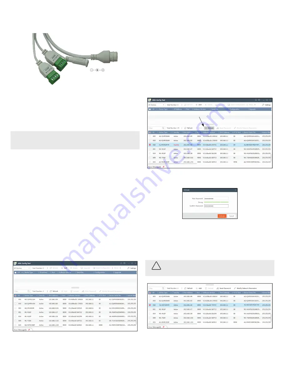
e. Connect the alarm extension cables to the Alarm IN and OUT terminals on the drop cable. Attach
the ground side of the sensor to the terminal marked
G
. Seal these connectors as needed to
prevent contamination by dust or moisture.
12 Vdc Power Connector
Alarm IN / OUT terminals
Audio
terminals
Ethernet connector
f. Connect the 12 Vdc power cables to the drop cable power connector, if needed. Observe the
polarity of the connector as shown in the picture above.
10. Attach the camera base assembly to the adapter plate using the three (3) machine screws provided.
Align the base assembly so that the locator pins on the adapter plate slip into the with the locator
holes on the base and that the camera is pointing at your surveillance target.
11. Apply power to the camera through the 12 Vdc extension cable or through the Ethernet cable using
PoE.
NOTE
This camera supports both IP (wired) and WiFi (wireless) connectivity. Steps 2 thru 4 below guide you for
activating the camera and configuring its network parameters for a wired connection. If using the camera
exclusively in wireless mode, please refer to the camera firmware user manual activating the camera and
configuring its network parameters, and then continue here with Step 5.
Step 2. Install the Alibi Config Tool software
NOTE:
If the camera LAN extension cable is attached to a Network Video Recorder (NVR) internal switch,
skip this step.
The Alibi Config Tool is a PC-based network utility for discovery of Alibi compatible devices. It provides
an easy way to activate devices, configure camera and recorder network configuration settings, and set
device passwords. It can be installed on a Microsoft® Windows® operating system that has direct access
to the network where your Alibi devices are installed. You can download the Alibi Configuration Tool from
Supercircuits.com
or
AlibiSecurity.com/Resources
.
1. Download the Alibi Config Tool from the
Supercircuits.com
or
AlibiSecurity.com/Resources
website. At the time when this document was published, the file is named:
alibi-config-tool.zip
and
is about 80MB.
2. Un-zip the file on a computer with Microsoft Windows (Windows 10 or newer) that is connected to
the LAN where your Alibi camera is connected.
3. Run the file contained in the zip file:
Alibi Config Tool.exe
. Follow the on-screen instructions to
install the file.
4. Open the Alibi Config Tool application. When the application opens, it automatically “discovers” and
lists all Alibi compatible devices on the LAN. See below.
Notice: In the screen above, the tool discovered devices with IP addresses of 192.168.0.xxx and
192.168.3.xxx. It will also list other Alibi compatible devices on the LAN, and devices with the
address 192.168.1.64 (an inactive Alibi device).
Step 3. Activate Inactive Alibi device
NOTE:
If the camera LAN extension cable is attached to a Network Video Recorder (NVR), skip this step.
Refer to the documentation available for your NVR firmware for the procedure to activate the camera, if
necessary.
When an Alibi device is first installed, or reset to its factory configuration, it must be “Activated” before it
can be used. In the Alibi Configuration Tool, “Inactive” devices have a
Security
status of
Inactive
, and
an IPv4 address of
192.168.1.64
. A device is “Activated” when a password is assigned to the
admin
username of the device.
In the example below, an ALI-NS1025VR camera is activated and configured for its network. The procedure
is similar for all other Alibi network cameras currently available.
1. Scan through the list of devices the Alibi Config Tool discovered for the Inactive device you want to
activate (see below). Click on the device in the list to highlight it, and then click the select box to check
it. See below.
Activate
2. Click the
Activate
button. In the Activate window, you will create a password for the
admin
(administrator) username.
a. In the Activate window, enter an a password for
admin
in the
New Password
field. Include a
combination of uppercase, lowercase alphabetic characters and numbers to create a “Strong”
password. The rating is shown beneath the field. See above.
b. Enter the
admin
password again in the
Confirm
field, and then click
Activate
. In the screen
below, notice that the device Security status shows “Active”.
Record your admin password
for reference later.
CAUTION
If you lose your
admin
(administrator) password, you cannot configure the device or restore
it to its factory settings. To reset your password,
call
your support organization for specific
instructions.
Notice that although the device is now activated, it retained the default IP address.


