26
Electrical installation
Type 8692, 8693
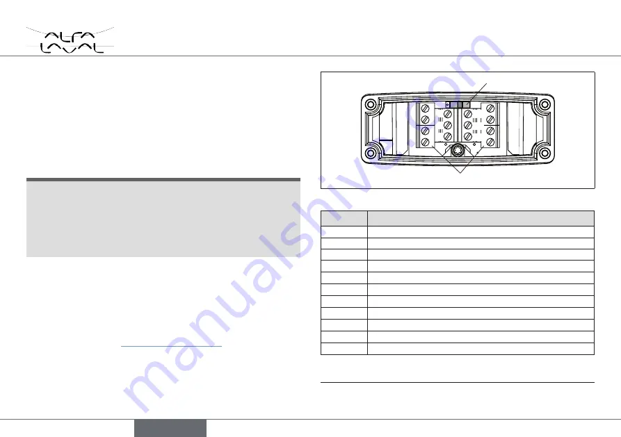
10.2.3. electrical installation with cable gland
procedure:
→
Unscrew the 4 screws at the cover and remove the cover. The
screw terminals are now accessible.
→
Push the cables through the cable gland.
→
Connect the wires.
noTe!
damage or malfunction due to penetration of dirt and humidity!
To ensure protection class IP65 / IP67:
• Tighten the union nut on the cable gland according to the cable
size or dummy plugs used (approx. 1.5 Nm).
• Close cover and crosswise tighten the 4 screws (maximum
torque 0.7 Nm).
When the supply voltage is applied, the positioner / process con-
troller is operating.
→
Make the required basic settings and actuate the automatic
adjustment of the positioner / process controller, as described in
the chapter entitled “11. Start-up Type 8692”.
Screw terminals
Switch
10
12
13
14
11
8
9
1
2
3
4
5
6
7
Fig. 15: Installation with cable gland
terminal configuration
11
Set-point value +
(0/4
–
20 mA / 0
–
5/10 V)
10
Set-point value GND
14
Supply v
24 V DC
13
Supply voltage
GND
12
9)
Binary input +
13
9)
Binary input GND
9
9)
Analogue position fe
8
9)
Analogue position feedback GND
5
9)
Binary output 1
6
9)
Binary output GND
7
9)
Binary output 2
Tab. 10: Installation with cable gland
9)
Option only.
english
Содержание 8692
Страница 38: ...38 Type 8692 8693 english...
Страница 74: ...74 Typ 8692 8693 deutsch...
Страница 111: ......
Страница 112: ......


