background image

101

Installation électrique

Type 8692, 8693

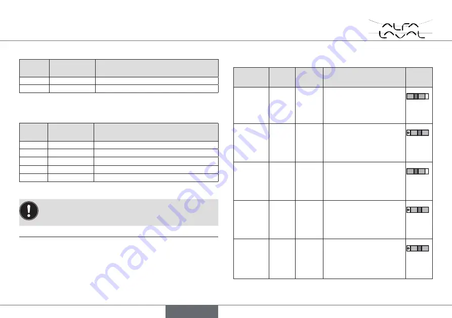
Connecteur rond M12 - 4 pôles (tension d’alimentation)

Broche couleur de 

fil

11)

affectation

1

brun

Tension d’alimen 24 V DC

3

bleu

Tension d’alimentation

GND

Tab. 12 :  Connecteur rond M12 - 4 pôles  (tension d’alimentation)

Douille M12 - 5 pôles (raccordement bus)

Broche couleur de 

fil

12)

signal

1

brun

VP+5

2

blanc

RxD/TxD-N

3

bleu

DGND

4

noir

RxD/TxD-N

5

gris

Schirm

Tab. 13 :  Douille M12 - 5 pôles (raccordement bus)

Pour des raisons de compensation de lignes, raccordez le 
capteur Pt 100 à l’aide de 3 conducteurs. Ponter obligatoi-
rement les broches 3 et 4 sur le capteur.


11) 

  Les couleurs indiquées se rapportent aux câbles de 
raccordement disponibles en tant qu’accessoires (918038).

12) 

 Les couleurs indiquées se rapportent aux câbles de 
raccordement disponibles en tant qu’accessoires (xxxxxx).

13) 

Réglable avec le logiciel.

14) 

 Les couleurs indiquées se rapportent aux câbles de 
raccordement disponibles en tant qu’accessoires (92903474).

Connecteur rond M8 - 4 pôles (valeur effective de process)  
- uniquement type 8693

type 
d’entrée

13)

Broche

couleur 
de fil

14)

affectation

inter-
rupteur

4 ... 20 mA 
- alimen-
tation interne


4

brun 
blanc 
bleu 
noir

Aliment. transm 24 V 
Sortie du transmetteur 
GND 
Pont après GND

Inter-
rupteur 
gauche

4 ... 20 mA 
- alimen-
tation 
externe


4

brun 
blanc 
bleu 
noir

Non affecté 
Eff. p 
Non affecté 
Eff. process -

Inter-
rupteur 
droit

Fréquence 
- alimen-
tation interne


4

brun 
blanc 
bleu 
noir

Alimentation c 24 V 
Entrée h 
Entrée horloge - (GND) 
Non affecté

Inter-
rupteur 
gauche

Fréquence 
-alimentation 
externe


4

brun 
blanc 
bleu 
noir

Non affecté 
Entrée h 
Entrée horloge - 
Non affecté

Inter-
rupteur 
droit

Pt 100 
(voir 
remarque à 
gauche)


4

brun 
blanc 
 
bleu 
noir

Non affecté 
Eff. process 1 (alimentation en 
courant) 
Eff. process 2 (GND) 
Eff. process 3 (compensation)

Inter-
rupteur 
droit

Tab. 14 :  Connecteur rond M8 - 4 pôles - type 8693

français

Содержание 8692

Страница 1: ...Quickstart English Deutsch Fran ais Type 8692 8693 Positioner Process Controller Positioner Prozessregler Positionneur R gulateur de process ESE02210EN DE FR...

Страница 2: ...reserve the right to make technical changes without notice Technische nderungen vorbehalten Sous r serve de modifications techniques 2011 2012 Alfa Laval A S Quickstart 1202 01_EU ML_00809647 Original...

Страница 3: ...ng levels 14 7 4 Display in operating state AUTOMATIC 15 8 Installation 15 8 1 Safety instructions 15 8 2 Installing the positioner process controller on process valves belonging to series 2103 and 23...

Страница 4: ...up Type 8692 31 11 1 Safety instructions 31 11 2 Specifying the basic settings 32 11 3 Automatic adjustment X TUNE 34 12 Start up Type 8693 35 13 Accessories 35 14 Safety Positions 36 15 Packaging Tra...

Страница 5: ...scription of the device can be found in the operating instructions for positioner Type 8692 and Type 8693 1 1 Symbols The following symbols are used in these instructions Danger Warns of an immediate...

Страница 6: ...ts recommended and authorized by Alfa Laval In view of the large number of options for use before installa tion it is essential to study and if necessary to test whether the positioner is suitable for...

Страница 7: ...e carried out by authorized technicians only and with the appropriate tools After an interruption in the power supply or pneumatic supply ensure that the process is restarted in a defined or controlle...

Страница 8: ...perating manual and its operating instructions as well as unauthorized tampering with the device release us from any liability and also invalidate the warranty covering the devices and accessories 4 G...

Страница 9: ...ed for a wide range of control tasks in fluid technology and depending on the application condi tions different process valves from the Alfa Laval range can be combined with the positioner or with the...

Страница 10: ...on of conformity the positioner Type 8692 and the process controller Type 8693 are compliant with the EC Directives 6 2 Standards Conformity with the EC Directives is verified by the following standar...

Страница 11: ...3 Type label example 6 6 Pneumatic data Control medium neutral gases air Quality classes in accordance with DIN ISO 8573 1 Dust content Class 5 max particle size 40 m max particle density 10 mg m Wate...

Страница 12: ...n frequency 0 1000 Hz 1 of measured value 300 mVss sine square triangle Pt 100 20 20 C resolution 0 1 C Input resistance for set point value signal 180 at 0 4 20 mA 12 bit resolution 19 k at 0 5 10 V...

Страница 13: ...f the display 7 1 Function of the keys Arrow key Change the display POS CMD Operating state AUTOMATIC Valve opens and closes manually operating state MANUAL MENU OPN MENU CLS Scroll in the menus Set n...

Страница 14: ...1 Press Switching from MANUAL AUTOMATIC MENU AUTO Press Tab 1 Changing the operating state 1 Only possible if POS CMD PV SP is displayed 7 3 Operating levels The positioner and the process controller...

Страница 15: ...nominal position 0 5 10 V 0 4 20 mA Tab 3 Display in operating state AUTOMATIC 8 Installation Only for positioner and process controller without pre assembled process valve 8 1 Safety instructions DAN...

Страница 16: ...ee Fig 8 Note Damaged printed circuit board or malfunction Ensure that the puck holder is situated flat on the guide rail Guide rail Puck holder Fig 7 Aligning the puck holder Push the positioner proc...

Страница 17: ...ar as the actuator and turn it into the required position Ensure that the pneumatic connections of the positioner process controller and those of the actuator are situated preferably vertically one ab...

Страница 18: ...function B As a result the spring chamber of the actuator is supplied with dry air from the vent duct of the positioner process controller Control function Pneumatic connection Type 8692 Type 8693 wi...

Страница 19: ...and an uncontrolled restart Secure system from unintentional activation Following installation ensure a controlled restart 9 2 Installing the process valve Thread type and dimensions can be found in...

Страница 20: ...r size 125 130 Fig 11 Pneumatic connection Caution Exhaust air concept In compliance with protection class IP67 an exhaust air line must be installed in the dry area Keep the adjacent supply pressure...

Страница 21: ...on 24 V DC Two kinds of connections are used for the electrical bonding of the positioner process controller Multi pole with circular plug in connector M12 x 1 8 pole Cable gland with screw terminals...

Страница 22: ...e position feedback 5 grey Analogue position feedback GND 4 yellow Binary output 1 3 green Binary output 2 2 brown Binary output GND 1 white Binary input Tab 6 Circular plug M12 8 pole input output si...

Страница 23: ...signed Clock input Clock input not assigned Switch on right Pt 100 see infor mation below 1 2 3 4 brown white blue black not assigned Process actual 1 current feed Process actual 2 GND Process actual...

Страница 24: ...imity switch at the setting screw to end position Switch off supply voltage at the proximity switch connector Bottom end position for control function I CFI Connect the pilot air Warning Valve moves a...

Страница 25: ...on Fig 13 3 Attach electronics module and close body Note Be careful not to damage the pins at the PCB When installing the electronics module observe positioning of the pins to the PCB on the electron...

Страница 26: ...um torque 0 7 Nm When the supply voltage is applied the positioner process con troller is operating Make the required basic settings and actuate the automatic adjustment of the positioner process cont...

Страница 27: ...s bridge Pin 3 and Pin 4 on the sensor 10 Can be adjusted by software 10 3 Electrical installation PROFIBUS DP The Quickstart only describes the electrical installation of the posi tioner process cont...

Страница 28: ...12 4 pole supply voltage Pin Wire color11 Configuration 1 brown Voltage supply 24 V DC 3 blue Voltage supply GND Tab 12 Circular plug M12 4 pole voltage supply Socket M12 5 pole bus connection Pin Wir...

Страница 29: ...ns of wire compensation connect the Pt 100 sensor via 3 wires Always bridge Pin 3 and Pin 4 on the sensor 10 4 Electrical installation DeviceNet The Quickstart only describes the electrical installati...

Страница 30: ...figuration 1 brown Voltage supply 24 V DC 3 blue Voltage supply GND Tab 15 Circular plug M12 4 pole voltage supply Circular plug M12 5 pole bus connection Pin Wire color16 Signal 1 Shielding 2 V 3 V 4...

Страница 31: ...plug M8 4 pole process actual value Type 8693 For reasons of wire compensation connect the Pt 100 sensor via 3 wires Always bridge Pin 3 and Pin 4 on the sensor 11 Start up Type 8692 To start up the...

Страница 32: ...1 Inputting the operating mode of the pneumatic actuator The operating mode of the actuator has been preset at the factory with the process valve mounted CFA and CFB single acting SINGLE CFI double a...

Страница 33: ...NPUT Selection INPUT menu MENU ENTER Press Change to INPUT menu Select 4 20 mA 0 20 mA 0 10 V or 0 5 V Selection of the input signal MENU SELEC Press Specifying the input signal MENU EXIT Press Exit I...

Страница 34: ...d by flow forces X TUNE MENU RUN approx 5 s X TUNE STARTED TUNE 0 INIT X TUNE READY Fig 20 Automatic adjustment X TUNE Procedure Key Action Description MENU MENU Hold pressed for 3 s countdown in the...

Страница 35: ...CONTROL additional function in the main menu via the configuration menu ADDFUNCTION Implement the standard settings for the process controller under P CONTROL For a detailed description of the start u...

Страница 36: ...A down pilot controlled control system down direct acting control system not defined Actuator system Designation Safety positions after failure of the auxiliary power electrical pneumatic up down sing...

Страница 37: ...ock resistant packaging Avoid exceeding or dropping below the permitted storage temperature Incorrect storage may damage the device Store the device in a dry and dust free location Storage temperature...

Страница 38: ...38 Type 8692 8693 english...

Страница 39: ...Funktion der Tasten 49 7 2 Betriebszustand 50 7 3 Bedienebenen 50 7 4 Anzeige im Betriebszustand AUTOMATIK 51 8 Montage 51 8 1 Sicherheitshinweise 51 8 2 Montage Positioner Prozessregler an Prozessve...

Страница 40: ...Typ 8692 67 11 1 Sicherheitshinweise 67 11 2 Festlegen der Grundeinstellungen 68 11 3 Automatische Anpassung X TUNE 70 12 Inbetriebnahme Typ 8693 71 13 Zubeh r 71 14 Sicherheitsstellungen 72 15 Transp...

Страница 41: ...er ts Die ausf hrliche Beschreibung des Ger ts finden Sie in der Bedie nungsanleitung f r den Typ 8692 und Typ 8693 1 1 Darstellungsmittel In dieser Anleitung werden folgende Darstellungsmittel verwen...

Страница 42: ...onenten einsetzen Angesichts der Vielzahl von Einsatz und Verwendungsf llen muss vor dem Einbau gepr ft und erforderlichenfalls getestet werden ob das Ger t f r den konkreten Einsatzfall geeignet ist...

Страница 43: ...von auto risiertem Fachpersonal mit geeignetem Werkzeug ausgef hrt werden Nach einer Unterbrechung der elektrischen oder pneumatischen Versorgung ist ein definierter oder kontrollierter Wiederanlauf...

Страница 44: ...nungsanleitung und ihrer Hinweise sowie bei unzul ssigen Eingriffen in das Ger t entf llt jegliche Haf tung unsererseits ebenso erlischt die Gew hrleistung auf Ger te und Zubeh rteile 4 Allgemeine Hin...

Страница 45: ...k nnen f r vielf ltige Regelungsaufgaben in der Fluidtechnik genutzt werden und je nach Einsatzbedingungen k nnen verschiedene Prozessventile aus dem Alfa Laval Programm mit dem Positioner oder dem P...

Страница 46: ...und der Prozessregler Typ 8693 sind konform zu den EG Richtlinien entsprechend der EG Konformit tserkl rung 6 2 Normen Durch folgende Normen wird die Konformit t mit den EG Richtlinien erf llt EN 6100...

Страница 47: ...ld 3 Typschild Beispiel 6 6 Pneumatische Daten Steuermedium neutrale Gase Luft Qualit tsklassen nach DIN ISO 8573 1 Staubgehalt Klasse 5 max Teilchengr e 40 m max Teilchendichte 10 mg m Wassergehalt K...

Страница 48: ...l sung 12 bit 17 k bei Frequenz 0 1000 Hz 1 v M 300 mVss Sinus Rechteck Dreieck Pt 100 20 220 C Aufl sung 0 1 C Eingangswiderstand f r Sollwertsignal 180 bei 0 4 20 mA Aufl sung 12 bit 19 k bei 0 5 10...

Страница 49: ...sten Pfeiltaste Wechsel der Anzeige POS CMD Betriebszustand AUTOMATIK Ventil manuell Auf und Zufahren Betriebszustand HAND MENU OPN MENU CLS Bl ttern in den Men s Einstellen von Zahlenwerten MENU MENU...

Страница 50: ...K HAND MENU MANU 1 dr cken Wechsel von HAND AUTOMATIK MENU AUTO dr cken Tab 1 Wechsel des Betriebszustands 1 nur bei Anzeige POS CMD PV SP m glich 7 3 Bedienebenen Der Positioner und der Prozessregler...

Страница 51: ...nzeige im Betriebszustand AUTOMATIK 8 Montage Nur f r Positioner und Prozessregler ohne vormontiertes Prozessventil 8 1 Sicherheitshinweise Gefahr Verletzungsgefahr durch hohen Druck in der Anlage Vor...

Страница 52: ...er plan auf der F hrungsschiene aufliegt F hrungsschiene Puckhalter Bild 7 Ausrichten des Puckhalters Den Positioner Prozessregler ohne Drehbewegung soweit auf den Antrieb schieben dass an der Formdic...

Страница 53: ...usrichten Darauf achten dass die pneumatischen Anschl sse des Positioners Prozessreglers und die des Antriebs vorzugs weise vertikal bereinander liegen siehe Bild 10 hinweis Durch ein zu hohes Drehmom...

Страница 54: ...en Steuerluftanschluss des Antriebs hergestellt werden Dadurch wird die Federkammer des Antriebs mit trockener Luft aus dem Entl ftungskanal des Positioners Prozessreglers versorgt Steuerfunktion Pneu...

Страница 55: ...iederanlauf gew hrleisten 9 2 Installation Prozessventil Gewindeart und Abmessungen sind dem entsprechenden Datenblatt zu entnehmen Das Prozessventil entsprechend der Bedienungsanleitung des Prozessve...

Страница 56: ...ine Abluft leitung in den trockenen Bereich montiert werden Den anliegenden Steuerdruck unbedingt mindestens 0 5 1 bar ber dem Druck halten der notwendig ist den pneumatischen Antrieb in seine Endstel...

Страница 57: ...rten Wiederanlauf gew hrleisten 10 2 Elektrische Installation 24 V DC F r den Positioner Prozessregler gibt es 2 Anschlussvarianten Multipol mit Rundsteckverbinder Kabelverschraubung mit Schraubklemme...

Страница 58: ...Stellungsr ckmeldung GND 4 gelb Bin rausgang 1 3 gr n Bin rausgang 2 2 braun Bin rausg nge GND 1 wei Bin reingang Tab 6 Rundstecker M12 8 polig Ein Ausgangssignale Rundstecker M12 4 polig Betriebsspan...

Страница 59: ...t Eingang Takt Eingang nicht belegt Schalter rechts Pt 100 siehe Hinweis unten 1 2 3 4 braun wei blau schwarz nicht belegt Prozess Ist 1 Stromspeisung Prozess Ist 3 GND Prozess Ist 2 Kompensation Scha...

Страница 60: ...r mit Schraubendreher an der Stellschraube auf End stellung einstellen Betriebsspannung am Initiatorstecker abschalten Untere Endstellung bei Steuerfunktion I Steuerluft anschlie en Warnung Ventilbewe...

Страница 61: ...aufsetzen und Geh use schlie en Hinweis Pins an Leiterplatte nicht besch digen Bei Montage des Elektronikmoduls die Positionierung der Pins zur Platine am Elektronikmodul beachten Elektronikmodul vor...

Страница 62: ...chraubung anziehen Drehmoment ca 1 5 Nm Den Geh usedeckel schlie en und die 4 Schrauben ber Kreuz anziehen Drehmoment maximal 0 7 Nm Nach Anlegen der Betriebsspannung ist der Positioner Prozess regler...

Страница 63: ...gt am Sensor br cken 10 3 Elektrische Installation PROFIBUS DP Der Quickstart beschreibt nur die elektrische Installation des Positi oners Prozessreglers und die Festlegung der Grundeinstellungen Die...

Страница 64: ...triebsspannung Pin Aderfarbe11 Belegung 1 braun Betriebsspannung 24 V DC 3 blau Betriebsspannung GND Tab 12 Rundstecker M12 4 polig Betriebsspannung Buchse M12 5 polig Bus Anschluss Pin Aderfarbe12 Si...

Страница 65: ...n anschlie en Pin 3 und Pin 4 unbedingt am Sensor br cken 10 4 Elektrische Installation DeviceNet Der Quickstart beschreibt nur die elektrische Installation des Positi oners Prozessreglers und die Fes...

Страница 66: ...braun Betriebsspannung 24 V DC 3 blau Betriebsspannung GND Tab 15 Rundstecker M12 4 polig Betriebsspannung Rundstecker M12 5 polig Bus Anschluss Pin Aderfarbe16 Signal 1 Schirm 2 V 3 V 4 wei CAN H 5 b...

Страница 67: ...s Leitungskompensationsgr nden ber 3 Leitungen anschlie en Pin 3 und Pin 4 unbedingt am Sensor br cken 11 Inbetriebnahme Typ 8692 F r die Inbetriebnahme des Positioners m ssen nach der Installation no...

Страница 68: ...ahltaste MENU EXIT dr cken 11 2 1 Eingabe der Funktionsweise des pneumatischen Antriebs Die Funktionsweise des Antriebs wird bei vormontiertem Prozessventil im Werk voreingestellt SFA und SFB einfachw...

Страница 69: ...n INPUT MENU ENTER dr cken Wechsel in Men INPUT 4 20 mA 0 20 mA 0 10 V oder 0 5 V ausw hlen Auswahl des Eingangssignals MENU SELEC dr cken Festlegen des Eingangssignals MENU EXIT dr cken Men INPUT ver...

Страница 70: ...en X TUNE MENU RUN ca 5 s X TUNE STARTED TUNE 0 INIT X TUNE READY Bild 20 Automatische Anpassung X TUNE Vorgehensweise Taste Aktion Beschreibung MENU MENU 3 s dr cken Countdown im Display Wechsel von...

Страница 71: ...s Die Zusatzfunktion P CONTROL ber das Konfiguriermen ADDFUNCTION ins Hauptmen aufnehmen Die Grundeinstellungen f r den Prozessregler unter P CONTROL vornehmen Eine detaillierte Beschreibung der Inbet...

Страница 72: ...hwirkend Steuerfunktion A down vorgesteuertes Stellsystem down direktwirkendes Stellsystem nicht definiert Antriebsart Bezeichnung Sicherheitsstellungen nach Ausfall der Hilfsenergie elektrisch pneuma...

Страница 73: ...n Eine ber bzw Unterschreitung der zul ssigen Lagertempe ratur vermeiden Elektrische Schnittstellen und die pneumatischen Anschl sse mit Schutzkappen vor Besch digungen sch tzen Falsche Lagerung kann...

Страница 74: ...74 Typ 8692 8693 deutsch...

Страница 75: ...et d affichage 85 7 1 Fonction des touches 85 7 2 Etat de marche 86 7 3 Niveaux de commande 86 7 4 Affichage en tat de marche AUTOMATIQUE 87 8 Montage 87 8 1 Consignes de s curit 87 8 2 Montage du pos...

Страница 76: ...92 104 11 1 Consignes de s curit 104 11 2 D termination des r glages de base 104 11 3 Adaptation automatique X TUNE 106 12 Mise en service type 8693 108 13 Accessoires 108 14 Positions de s curit 109...

Страница 77: ...eil dans le manuel d utilisation du type 8692 et type 8693 1 1 Symboles Les moyens de repr sentation suivants sont utilis s dans les pr sentes instructions de service Danger Met en garde contre un dan...

Страница 78: ...u s par Alfa Laval tant donn la multitude de cas d utilisation il convient de v rifier et si n cessaire tester avant montage si le positionneur convient pour le cas d utilisation concret Les condition...

Страница 79: ...ation ne peut pas tre actionn e par inadvertance Les travaux d installation et de maintenance doivent tre effectu s uniquement par des techniciens qualifi s et habilit s disposant de l outillage appro...

Страница 80: ...ec ses consignes ainsi que les interventions non autoris es sur l appareil excluent toute responsabilit de notre part et entra nent la nullit de la garantie l gale concernant les appareils et les acce...

Страница 81: ...hnique des fluides et selon les conditions d utilisation il est possible de combiner diff rentes vannes de processus du programme Alfa Laval avec le positionneur Sont appropri es les vannes si ge incl...

Страница 82: ...el externe 6 Caract ristiques techniques 6 1 Conformit Le positionneur type 8692 et type 8693 sont conformes aux direc tives CE sur la base de la d claration de conformit CE 6 2 Normes La conformit av...

Страница 83: ...Caract ristiques pneumatiques Fluide de commande gaz neutres air Classes de qualit selon DIN ISO 8573 1 Teneur en poussi res Classe 5 Taille maximale des particules 40 m densit maximale des particules...

Страница 84: ...uence 0 1 000 Hz 1 de la valeur mesur e 300 mVss sinus rectangle triangle Pt 100 20 220 C r solution 0 1 C R sistance d entr e pour signal valeur de consigne 180 0 4 20 mA r solution 12 bit 19 k 0 5 1...

Страница 85: ...l cran 7 1 Fonction des touches Touche fl ch e Changement de l affichage POS CMD Etat de marche AUTOMATIQUE Ouverture et fermeture manuelles de la vanne tat de marche MANUEL MENU OPN MENU CLS Parcour...

Страница 86: ...NUEL AUTOMATIQUE MENU AUTO appuyer Tab 1 Changement d tat de marche 1 possible seulement avec l affichage POS CMD PV SP 7 3 Niveaux de commande Le positionneur et le r gulateur de process poss dent 2...

Страница 87: ...ichage en tat de marche AUTOMATIQUE 8 Montage Uniquement pour positionneur sans vanne process pr mont e 8 1 Consignes de s curit DANGER Danger d la haute pression Avant de desserrer les conduites et l...

Страница 88: ...ur repose bien plat sur le rail de guidage Rail de guidage Support de rouleau presseur Fig 7 Disposition du support de rouleau presseur et du manchons Glisser le positionneur sur l actionneur sans la...

Страница 89: ...sposer dans la position souhait e en le faisant tourner Veillez ce que les raccordements pneumatiques du posi tionner et ceux de l actionneur soient de pr f rence super pos s voir Fig 10 Remarque Le t...

Страница 90: ...raccord de l actionneur Ainsi la chambre ressort de l actionneur est aliment e en air sec partir du canal d chappement du positionneur Fonction Raccordement pneumatique type 8692 8693 l actionneur Sor...

Страница 91: ...s d la mise en marche involontaire de l installation et le red marrage non contr l Emp chez tout actionnement involontaire de l installation Garantissez un red marrage contr l apr s le montage 9 2 Ins...

Страница 92: ...actionneur 125 130 Fig 11 Raccordement pneumatique Attention concept d vacuation d air Pour le respect du type de protection IP67 il convient de monter une conduite d vacuation d air dans la zone s ch...

Страница 93: ...tr l apr s le montage 10 2 Installation lectrique 24 V DC Il existe deux types de raccordement pour r aliser le contact lec trique du positionneur Multip le avec connecteur rond M12 x 1 8 p les Presse...

Страница 94: ...oche Couleur de fil4 Affectation 8 rouge Valeur de consigne 0 4 20 mA 0 5 10 V 7 bleu Valeur de consigne GND Tab 5 Connecteur rond M12 8 p les valeur de consigne Connecteur rond M12 8 p les signaux d...

Страница 95: ...rapportent aux c bles de raccordement disponibles en tant qu accessoires 92903474 Connecteur rond M8 4 p les valeur effective de proc dure uniquement type 8693 Type d entr e6 Broche Couleur de fil7 A...

Страница 96: ...remise sous tension par inadvertance Veuillez respecter les r glementations en vigueur pour les appa reils lectriques en mati re de pr vention des accidents ainsi qu en mati re de s curit Proc dure s...

Страница 97: ...B Placer le cavalier voir Fig 13 R glage des fin de course Raccorder l air de pilotage Avertissement D placement de la vanne apr s application de la tension lectrique Apr s application de la tension...

Страница 98: ...ert 10 2 3 Installation lectrique avec presse toupe Proc dure suivre D visser les 4 vis du couvercle du corps et le retirer Les bornes viss es sont maintenant accessibles Pousser les c bles travers le...

Страница 99: ...broches 3 et 4 sur le capteur 9 Uniquement l option Valeur effective de proc dure type 8693 Type d entr e10 Broche Affectation Interrupteur 4 20 mA alimentation interne 1 2 3 4 Aliment transmetteur 24...

Страница 100: ...la terre adapt Pour garantir la compatibilit lectromagn tique CEM faire en sorte que le c ble soit le plus court possible 30 cm max 1 5 mm2 Apr s application de la tension d alimentation le positionn...

Страница 101: ...ciel 14 Les couleurs indiqu es se rapportent aux c bles de raccordement disponibles en tant qu accessoires 92903474 Connecteur rond M8 4 p les valeur effective de process uniquement type 8693 Type d e...

Страница 102: ...la terre adapt Pour garantir la compatibilit lectromagn tique CEM faire en sorte que le c ble soit le plus court possible 30 cm max 1 5 mm2 Apr s application de la tension d alimentation le positionn...

Страница 103: ...Les couleurs indiqu es se rapportent aux c bles de raccordement disponibles en tant qu accessoires 92903474 Connecteur rond M8 4 p les valeur effective de process uniquement type 8693 Type d entr e13...

Страница 104: ...t et l utilisation conforme L appareil l installation doit tre mis e en service uniquement par un personnel suffisamment form 11 2 D termination des r glages de base Apr s application de la tension de...

Страница 105: ...ENTER DOUBLE Fig 18 Structure de commande ACTUATOR Seulement apr s avoir quitt le menu principal avec la touche de s lection gauche MENU EXIT les donn es modifi es ne sont enregistr es dans la m moir...

Страница 106: ...e l ex cution de X TUNE sous pression de service il y a un risque imminent de blessures N ex cutez jamais X TUNE lorsque le process est en cours Evitez l actionnement involontaire de l installation pa...

Страница 107: ...a progression de X TUNE l cran TUNE 1 Message apr s la fin de X TUNE l cran X TUNE READY 19 appuyer une touche au choix Quitter le menu X TUNE MENU EXIT appuyer Changement de niveau de r glage Niveau...

Страница 108: ...suppl mentaire P CONTROL dans le menu principal via le menu de configuration ADDFUNCTION Effectuez les r glages de base du r gulateur de process sous P CONTROL Vous trouverez une description d taill...

Страница 109: ...action pilot e down syst me de r glage action directe non d fini up down simple effet Fonction B up syst me de r glage action pilot e up syst me de r glage action directe non d fini Type d actionneur...

Страница 110: ...ocs vitez le d passement vers le haut ou le bas de la temp rature de stockage admissible Un mauvais stockage peut endommager l appareil Stockez l appareil au sec et l abri des poussi res Temp rature d...

Страница 111: ......

Страница 112: ......

Отзывы: