background image

SFBTT20-IT BOBTAIL® Hydraulic Tool

(HK1121)

Alcoa Fastening Systems

9

Figure 4

128441-3 C

128441-3 C

ONTROLLER

ONTROLLER

UL & Serial
No. Sticker

Instructions &

Wiring Diagram

Digital

Display

PLC

Arrow
Buttons

Command

Buttons

ESC - MENU - ENT

3-Position

Mode

Switch

A

S

 S

HIPPED

:

Controller Pressure:

4200 psi.

Hold Timer:

500 (.50 seconds).

Eject Timer:

600 (.60 seconds).

1. Move the 3-Position Mode Switch on the PLC to

“STOP” (right-most position).

2. Press the 

MENU

Command Button to enter the

“Monitor” menu.

3. Press the 

ENT

Command Button to select “Data

Monitor”. Press 

ENT

again to select “V” data type.

4. Enter the address button of the value you need to

alter. Use the left (◄ ) and right ( ►) buttons to
position the cursor. Use the up ( ▲ ) and down 
( ▼ ) buttons to change individual digits. Press
the 

ENT

Command Button when finished.

5. Press the 

ENT

Command Button to enter the

“Change” menu.

6. Use the arrow buttons again to enter the new

value. Press 

ENT

when finished.

7. Press the 

ESC

Command Button 5 times to exit.

8. Move the Mode Switch back to “RUN” (left-most

position).

9. Check the continuously scrolling display for your

new value before using the Tool again.

“V“

ADDRESS

DESCRIPTION

RANGE

DEFAULT UNITS

07411

T1 Press. SetPt  1000-9999

4200

psi

07412

T2 Press. SetPt 1000-9999

4200

psi

07413

T3 Press. SetPt 1000-9999

4200

psi

07421

T1 Hold Timer

0-3000

500

msec

07422

T2 Hold Timer

0-3000

500

msec

07423

T3 Hold Timer

0-3000

500

msec

07431

T1 Eject Timer

250-3750

600

msec

07432

T2 Eject Timer

250-3750

600

msec

07433

T3 Eject Timer

250-3750

600

msec

SET POINT ADJUSTMENTS

The active set points are displayed continuously while the Controller is in RUN mode. Stopping the Controller (which
also stops Tool sequencing) allows the user to enter the Controller menu to make adjustments. 

Do not begin this

procedure if any of the Tools are still in use.

M 3

:

D A T A

T Y P E

V

A D D R E S S

0 0 0 0 0

M 3

:

>

D A T A

M O N

I

T O R

> B

I

T

M O N

I

T O R

M 3

:

D A T A

V

0

C H G =

0

0 0 0

0 0 0 0

Содержание SFBTT20-IT SFBTT20-IT

Страница 1: ...12 05 2013 HK1121 INSTRUCTION MANUAL BOBTAIL INSTALLATION SYSTEM SFBTT20 IT SFBTT20 IT...

Страница 2: ...SFBTT20 IT BOBTAIL Hydraulic Tool HK1121 Alcoa Fastening Systems 2...

Страница 3: ...ON FOR USE 6 TOOL TO POWERIG SET UP 7 8 CONTROLLER 9 OPERATING INSTRUCTIONS 10 WRENCHING UP OF PIPE THREADS 10 LIMIT SWITCH ADJUSTMENT 10 MAINTENANCE 11 TOOL ASSEMBLY PARTS LIST 12 TOOL ASSEMBLY DRAWI...

Страница 4: ...s it is likely for these not to allow counteracting of nor mal or unexpected tool movement 8 If the assembly power tool is fixed to a suspension device make sure that fixation is secure 9 Beware of th...

Страница 5: ...LE OF OF O OPERATION PERATION S SPECIFICATIONS PECIFICATIONS Power Source Huck POWERIG Hydraulic Unit Hose Kits Use only genuine HUCK Hose Kits rated 10 000 psi working pressure Hydraulic Fluid ATF me...

Страница 6: ...ead full manual before using tool A half hour training session with qualified personnel is recommended before using Huck equipment When operating Huck installation equip ment always wear approved eye...

Страница 7: ...ve handle gradually counterclock wise turn clockwise to increase pressure 1 With the Nose Assembly in place on the Installation Tool begin setup 2 Connect the Hydraulic Hoses to the Powerig 3 Connect...

Страница 8: ...E and Table 1 12 Using a load cell see PHOTO A or a skid more and a test fastener in the tool energize the Powerig using a trigger switch Adjust the Relief Valve see PHOTO B so the tool gen erates the...

Страница 9: ...s again to enter the new value Press ENT when finished 7 Press the ESC Command Button 5 times to exit 8 Move the Mode Switch back to RUN left most position 9 Check the continuously scrolling display f...

Страница 10: ...res 5 and 6 on pages 13 and 14 for identification of Components NOTE It is important to ensure that the face of the micrometer is firmly against the Puller Head and the micrometer depth pin is in cont...

Страница 11: ...em to detect and correct minor troubles At the beginning of each shift day Inspect tool and nose assembly for external dam age Verify that hydraulic hose fittings couplings and electrical connections...

Страница 12: ...03431 2 15 Female Coupler 110439 1 16 Male Coupler 110438 1 17 Switch Housing Assy 129300 1 17a Switch Housing 128980 1 17b Limit Switch Lever 128823 1 17c Compression Spring 508368 1 17d Set Screw 50...

Страница 13: ...4 not shown 16 14 SECTION A A 17 See Figure CC for details 18 4 18 2 22 4 22 8 19 20 21 23 24 Note 1 Apply Loctite 242 HUCK part number 505016 per manufacturer s instructions to these threaded joints...

Страница 14: ...turer s instructions to these threaded joints Vibra TITE is a registered trademark of ND Industries 2 Tighten Setscrew 17h against Setscrew 17d until Setscrew 17d turns with difficulty Notes 1 2 D D C...

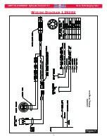
Страница 15: ...SFBTT20 IT BOBTAIL Hydraulic Tool HK1121 Alcoa Fastening Systems 15 W WIRING IRING D DIAGRAM IAGRAM 129202 129202 129202 Wiring Diagram Figure 7...

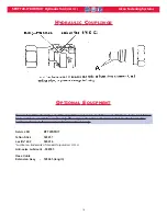
Страница 16: ...rk of Henkel Corporation U S A Anti seize Lubricant 508183 Hose Cable Extension Assy 128461 length To maintain CE conformity only CE compatible equipment should be used with these tools Installation t...

Страница 17: ...nety 90 day warranty period for tooling other items nonstandard or custom products described above and Huck shall inspect products for which such claim is made TOOLING PART S AND OTHER ITEMS NOT MANU...

Страница 18: ...nization Alcoa Fastening Systems AFS maintains company offices throughout the United States and Canada with subsidiary offices in many other countries Authorized AFS distributors are also located in m...

Отзывы: