2024 series Tooling
(HK1077)
Alcoa Fastening Systems
6
P
RINCIPLE
OF
O
PERATION
PULL PISTON
SPRING
DAMPER VALVE
EXHAUST
AIR PISTON
Hydraulic Oil
Air Pressure
Exhaust Air
HYDRAULIC
PISTON
THROTTLE VALVE
(PULL POSITION)
HYDRAULIC
PISTON
THROTTLE VALVE
(RETURN POSITION)
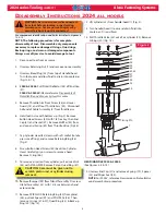
When the trigger is depressed the thro le valve moves to
down posi on, pressurized air is directed to the bo om of
the air piston, causing the piston to move upward (Fig.1a).
The air above the piston is exhausted and directed through
the center of the thro le valve and out the bo om of the
tool.
As the hydraulic rod moves upward, a column of
fl
uid is
forced into head, which moves the pull piston back. The
a ached nose assembly moves with the pull piston to start
fastener installa on.
When fastener installa on is completed, the trigger is
released. Air pressure with the assistance of a spring
causes the thro le valve to return to its up posi on.
Pressurized air is re-directed to the top of the air piston
(Fig.1b), causing the air piston and hydraulic rod to move
downward.
The air from below the piston is exhausted through the
bo om of the tool. Spring pressure returns the pull piston
to its home posi on. The damper valve impedes oil
fl
ow at
pinbreak helping prevent “Tool Kick”.
Fig. 1a
Fig. 1b
P
REPARATION
FOR
U
SE
The Model 2024 Installa on Tool is shipped with a plas c
plug in the air inlet connector. The connector has 1/4-18
female pipe threads to accept the air hose
fi
ng. Quick
disconnect
fi
ngs and 1/4” inside diameter air hose are
recommended. An air supply of 90 psi
(6.2 bar)
capable of
20 ³/s
(.57 m
³/s
)
must be available. Air supply should be
equipped with a
fi
lter-regulator-lubricator unit.
1. Remove plas c shipping plug from Air Inlet Connector
and put in a few drops of Automa c Transmission Fluid,
DEXRON III, or equivalent.
2. Screw quick disconnect
fi
ng into Air Inlet Connector.
3.
Set air pressure on regulator to 90-100 psi.
4. Connect air hose to tool.
5. Cycle tool a few mes by depressing and releasing
trigger.
6. Disconnect air hose from tool.
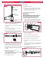
7. Remove Retaining Nut.
8. Select proper Nose Assembly for fastener to be
installed.
9. Screw Collet Assembly (including lock collar and shim if
applicable) onto Spindle. (Wrench Tight)
10. Slide Anvil over Collet Assembly and into counterbore.
11. Slide Retaining Nut over Anvil and screw Nut onto
Head.
12. Connect air hose to tool and install fastener(s) in test
plate of proper thickness with proper size holes. Inspect
fastener(s).
NOTES:
1. Air quick disconnect
fi
ngs and air hoses are not
available from Huck Interna onal, Inc.
2. On old style nose assemblies with lock collars,
Vibra-
TITE
should be used on collect threads, since there
is no staking hole provided on the 2024 pull piston.
Refer to nose assembly data sheets.
CAUTION: Do not use TEFLON tape on
threads. Use TEFLON in stick form only:
Huck P/N 503237


