2024 series Tooling
(HK1077)
Alcoa Fastening Systems
11
General Assembly (continued):
(Refer to Figures 2 & 9)
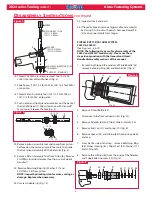
14. Install Quad Ring (47) onto Air Piston (37).
15. Lubricate piston rod. Press assembled air piston/
rod into cylinder just enough to allow installation
of cylinder head (45).
16. Assemble O-Ring (46) onto Cylinder Head (45)
and then push Cylinder Head squarely into
cylinder taking care not to damage O-ring (46).
Install Retaining Ring (38).
(Align screw holes
with muffl er end cap)
17. Position Muffl er (42) in center of cylinder head.
Position Gasket (39) on cylinder. ( Refer to Fig 2
& 9)
Note direction of Lip
18. Carefully position Bottom Plate (41) on cylinder.
NOTE: Make sure that the muffl er is properly
positioned in recess of Bottom Plate (41).
(Figures 2 & 14).
19. Secure the bottom plate with the three Button
Head Screws (40) using 1/8 hex key (Fig. 2).
20. Assembly O-Rings (50) on Throttle Valve (52).
(Fig. 14 Section CC)
21. Place the tool upright on a level surface, drop
Spring (49) into throttle valve bore in cylinder (35).
Push Throttle Valve into
cylinder.
22. Place ball end of Throttle Cable (2) into end of
Throttle Arm (53), then slide Throttle Arm into slot
on Cylinder (Fig. 9).
23. Snap Lever Guard (73) in place, and install Pivot
Screw (48) in cylinder to retain throttle arm (53).
24.
For 2024 & 2024L:
Push Pintail Defl ector (24)
onto End Cap (21).
For 2024V & 2024LV: Please reference
Disassembly of Pintail Bottle and Vacuum System
Procedure.
25. Tool is now completely assembled and needs to
be fi lled with oil. Please refer to the fi ll and bleed
section next.
Pintail Bottle/Vacuum 2024V & 2024LV:
(Refer to Figures 6 & 15 )
The following steps are for the assembly of the 2024V
& 2024LV models only. Please use these steps in
conjunction with the General and Head/Handle
disassembly sections of this manual.
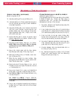
1. Assemble Adapter and Tube/Side Assembly (70)
and new O-Rings (65).
2. From bottle side of End Cap (21) install O-Ring
(69), Washer (71), Wiper Seal (23), Wiper Housing
(67) and Retaining Ring (66) as shown in (Fig. 6).
3. From tool side of end cap install O-Ring (68),
Spacer (22) and Spring (19). (as shown in Fig. 6)
Screw entire assembly into head and tighten.
4. Assemble Tube/Slide Assembly and O-rings (65),
slide complete assembly onto End Cap (21) and
push tube into connector (54) (Fig.15).
5. Position Adapter (64) and pintail bottle (24) on
End Cap (21) (Fig. 5 & 15).
6. By reaching through the window of the Pintail
Bottle (24), install Washer (63) and Retaining
Ring (62) as shown in (Fig. 5).
A
SSEMBLY
I
NSTRUCTIONS
continued


