23
Nov. 2006
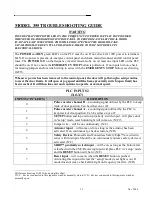
MODEL 355 TROUBLESHOOTING GUIDE
WARNING
ENSURE THAT THE POWER LED ON THE FREQUENCY INVERTER IS FULLY EXTINGUISED
WHENEVER DE-ENERGIZING CONTROL PANEL TO PERFORM ANY ELECTRICAL WORK
(WAIT AT LEAST 30 SECONDS). THIS WILL INDICATE THAT THE HIGH VOLTAGE
CAPACITORS HAVE BEEN FULLY DRAINED. FAILURE TO WAIT MAY RESULT IN
ELECTRICAL SHOCK.
The POWER and RUN green LED’s on the PLC must be on. If not, check for 120V power to terminals
L&N. If no power is present, de-energize control panel and check main disconnect and all control panel
fuses. The POWER LED on the frequency inverter must also be on. At least one input LED on the PLC
should be on. If not, ensure the EMERGENCY STOP button is pulled out. If no inputs turn on, check
for missing jumpers and/or switch wiring in series with the EMERGENCY STOP button; see drawing
#AF35.
Whenever power has been removed to the control panel, the door will go through a setup routine
to reset the door limits. It will open at jog speed until the home proximity switch (open limit) has
been reached. It will then time out and continue to operate at normal speed.
PLC INPUTS2
(X0-X7)
INPUTS (“IN” LED’S)
DESCRIPTION
0
Pulse encoder channel B – a counting signal utilized by the PLC to keep
track of door position. Can be either on or off.
1
Pulse encoder channel A – a counting signal utilized by the PLC to
keep track of door position. Can be either on or off.
2
SETUP button and top overrun proximity switch input – will place door
in “setup” mode, reset button light will come on. (N/C)3
3
Jumper wire – will be on continuously. (N/C)
4
Actuator input – will come on for as long as the actuator has been
activated. If on continuously, check actuators.(N/O)
5
Safety Devices. Photocells and Contactless Safety Edge™ are wired in
series with this input. Should be on continuously unless a safety device is
activated. (N/C)
6
SRD2™ proximity switch input – will be on as long as the bottom rail
is latched with the CSE. Removing input will place PLC in “setup” mode
and the RESET button will be lit. (N/C)
7
Reset input – will come on when the RESET button is pushed.
Activating this input will clear the “setup” mode (reset light is on). If
mode does not clear, check alarm light on frequency inverter. (N/O)
2 Reference drawing #AF35 when using this chart.
3 N/C – devices connected to this input are wired as normally closed; N/O – devices connected to this input are wired as
normally open.
Содержание 350016-0000
Страница 3: ......
Страница 12: ...12 Nov 2006 Figure 6 Figure 7 ...
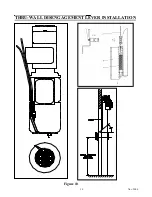
Страница 14: ...14 Nov 2006 THRU WALL DISENGAGEMENT LEVER INSTALLATION Figure 10 ...
Страница 20: ...20 Nov 2006 ...


