


ASSEMBLY OF YOUR MODEL 140
9
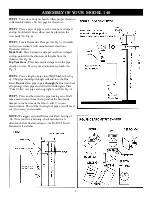
STEP 1
Place stove body on hearth. Allow proper clearance
to flammable surfaces. See last page for clearances.
STEP 2
Place a piece of pipe over the vent hole, crimped
end up. For Model 140 an elbow may be placed on the
stove body
(See Fig. 8).
STEP 3
Locate Barometric Damper
(See Fig. 5).
Assemble
and set in accordance with manufacturer’s directions.
Proceed as follows:
Model 140
- Place barometric damper on elbow, crimped
end up, pointed in the direction of thimble from the
chimney
(See Fig. 8).
Top Vent Stove
- Place barometric damper over the pipe
already on stove. Be sure your attachment is plumb.
(See
Fig. 5).
STEP 4
Place a length of pipe into Wall Thimble
(See Fig.
4).
This pipe should go through wall and into the Flue
Liner.
Do not
allow pipe to pass
through
the flue liner. Seal
all openings where pipe entered wall with fiberglass. Place
“Trim Collar” over pipe and snug tight to wall
(See Fig. 4).
STEP 5
Place an elbow into the pipe coming out of wall,
take a measurement from the top end of the barometric
damper to the bottom of the elbow - add 3" to your
measurements. This will be the length of pipe you will need
cut
(if necessary)
and assemble.
NOTE:
We suggest an initial Barometric Draft Setting of
.04. Once your fire is burning, check manufacturer’s
directions before final adjustment - use Rc-Bt Ul Listed
Barometric if available.


