background image

Use these instructions in conjunction with the complete installation

manual for this product.

Your Alarm.com Dealer Portal:

www.alarm.com/dealer

The Mobile Tech App:

https://alarmadmin.alarm.com/mobile

Sign in using the dealer credentials provided by Alarm.com.

Create a customer account

a. From the Alarm.com Dealer website or MobileTech app, select

Customers >

Create New Customer

.

b. Add the customer’s address and contact information.

c. Enter the 10-digit serial number, located on the barcode sticker of the panel.

Install the panel

a. Inspect the panel and peripheral devices before installation to ensure they are
not damaged.

b. Install the iotega on a flat, stable surface, free from vibration and shock, and
near a power outlet.

c. Connect the panel to the Customer’s router with a CAT-5/6 Ethernet cable.

d. Pull out the battery tape.

e. Connect the barrel jack of the plug-in adapter to the power connector on the
back of the panel. Route the power cable through the strain relief channel on the
bottom of the panel then plug the adapter into an AC outlet.

The iotega powers up once plugged in. The power-up sequence is as follows:

l

The integrated keypad numbers illuminate in sequence.

l

The Power LED illuminates after approximately 40 seconds.

l

The Ethernet Link Speed LED illuminates steady green and the
Ethernet Link Activity LED flashes rapidly to indicate that a
connection is being made.

l

The Remote Connection LED illuminates steady green to indicate a
connection to the Alarm.com server has been made over Cell or
Ethernet.

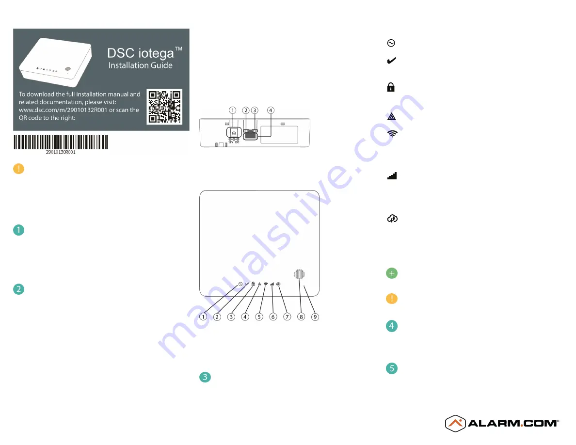
1. Power Connector

2. Ethernet Link Speed LED

3. Ethernet Link Activity LED

4. Ethernet Port

1. Power LED

6. Cellular Signal Strength LED

2. Ready to Arm LED

7. Remote Connection LED

3. Armed LED

8. Siren

4. Trouble LED

9. Microphone

5. WiFi Signal Strength LED

Verify panel communications

Review the LED indicators on the iotega panel.

LED operational status is shown below.

Power

On steady (green) when AC power is connected.

Ready to Arm

On steady (green) when partition is in a ready to arm mode. No fire or CO
alarms are present.

Armed

On steady (red) when partition is armed.

Off when partition is disarmed or audible alarm annunciation is off.

Trouble

On steady (amber) when system troubles are present.

Wi-Fi® Signal Strength

On steady (green) when strong signal connection .

On steady (amber) when weak signal connection.

On steady (red) when no signal, Off when no Wi-Fi detected.

Cellular Signal Strength

On steady (green) when strong signal connection .

On steady (amber) when weak signal connection.

On steady (red) when no signal or no connection detected.

Remote Connection Status

On steady (green) when Link to remote server is active.

On flashing (red) when link to remote server is active but has failed to
communicate.

Off when link to remote server is not active.

For more information on LED indicators, see “Controls and

Indicators” in the iotega installation manual.

When replacing the battery, use a battery pack suitable for the

application. Refer to “Specifications” in the iotega installation
manual.

Confirm signaling with the Alarm.com backend

On MobileTech or the Dealer Portal, navigate to

Remote Toolkit

and run the

communication test. This test confirms the unit is communicating with
Alarm.com.

Enroll sensors (zones) and peripheral devices

Navigate to

Equipment > Sensors > Add a Sensor

to put the panel into Add

Mode. Select Auto-Learn or Remote Add.

Содержание DSC iotega

Страница 1: ...Ethernet Link Activity LED 4 Ethernet Port 1 Power LED 6 Cellular Signal Strength LED 2 Ready to Arm LED 7 Remote Connection LED 3 Armed LED 8 Siren 4 Trouble LED 9 Microphone 5 WiFi Signal Strength L...

Страница 2: ...a the installer portal and control the system from the end user mobile app and web portal For information on using the iotega and adding Z Wave devices or cameras please refer to the online user manua...

Страница 3: ...includes computer software and may include associated media printed materials and online or electronic documentation Any software provided along with the SOFTWARE PRODUCT that is associated with a se...

Страница 4: ...EGSM EDGE 880MHz 915MHz Class 4 2W 900 MHz E GSM Class E2 0 5W 900 MHz EDGE DCS EDGE 1710MHz 1785MHz Class 1 1W 1800 MHz DCS Class E2 0 4W 1800 MHz EDGE FDD Band VIII 880MHz 915MHz FDD Band I 1920MHz...

Страница 5: ...e connexion distance passe au vert fixe pour indiquer qu une connexion au serveur Alarm com a t tablie via le r seau cellulaire ou Ethernet 1 Connecteur d alimentation 2 Voyant lumineux de vitesse de...

Страница 6: ...la v rification du syst me afin de confirmer que le syst me fonctionne correctement Si un probl me ou une panne se d clare s lectionnez Examiner et r soudre les probl mes pour plus de d tails Le syst...

Страница 7: ...curity Controls n acceptera aucun envoi pour lequel une autorisation pr alable n aura pas t obtenue Les produits que Digital Security Controls juge tre r parables seront r par s et renvoy s Les frais...

Страница 8: ...clients ainsi que des dommages la propri t ATTENTION DSC recommande de tester compl tement et r guli rement l ensemble du syst me Toutefois malgr des tests r guliers il peut arriver que le fonctionne...

Страница 9: ...conexi n con el servidor de Alarm com se ha realizado a trav s de una conexi n celular o Ethernet 1 Conector de alimentaci n 2 LED de velocidad de enlace de Ethernet 3 LED de actividad de enlace de Et...

Страница 10: ...p gina Realizar comprobaci n del sistema Navegue hasta Remote Toolkit Ejecutar comprobaci n del sistema para confirmar que el sistema funciona correctamente Si se presenta un problema o condici n de...

Страница 11: ...de autorizaci n Digital Security Controls no aceptar ning n cargamento sin un n mero de autorizaci n primero Los productos que Digital Security Controls Ltd determine que son reparables ser n reparado...

Страница 12: ...talaciones o servicios tiempo de inactividad tiempo del comprador reclamaciones de terceros incluyendo clientes y da os a la propiedad ADVERTENCIA DSC recomienda que se pruebe todo el sistema completa...

Страница 13: ...Ethernet 1 Conector de energia 2 LED Velocidade do link Ethernet 3 LED Atividade do link Ethernet 4 Porta Ethernet 1 LED Alimenta o 6 LED Intensidade do sinal de celular 2 LED Pronto para armar 7 LED...

Страница 14: ...fica o do sistema para confirmar se o sistema est funcionando corretamente Se um problema ou uma condi o de erro ocorrer consulte Revis o e resolu o de problemas para mais detalhes O Sistema de Segura...

Страница 15: ...iza o pr via Os produtos que a Digital Security Controls determina como sendo repar veis ser o reparados e devolvidos Uma taxa estabelecida a qual a Digital Security Controls predeterminou e que pode...

Страница 16: ...associado custo de capital custo do equipamento substitu do recursos ou servi os tempo parado tempo do comprador reclama es de terceiros incluindo clientes e preju zos propriedade AVISO a DSC recomen...

Отзывы: