GB 2
GB
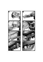
b) Bowden cable for the wheel drive
The Bowden cable for the drive is on the right
side of the housing viewed in the direction of
travel.
16
.
Unscrew hexagonal screw on housing (on
left viewed in the direction of travel).
17
.
Screw Bowden cable guide onto
housing – check orientation: Lipped edge
of guide must point upwards.
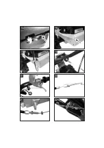
Thread the Bowden cable through the
guide.
18
.
Thread the Bowden cable through the guide
on the console.
19
.
Insert the bent hook of the Bowden cable
into the lower hole on the outward side of
the handlebar lever.
Unscrew the foremost nut on the adjuster "
a"
.
Insert the adjuster in the holder and
retighten the nut.
Set the lower adjuster on the housing to
its middle position.
c) Bowden cable for cutter bar
The Bowden cable for the cutter bar is on the
left side of the housing viewed in the direction
of travel.
20
Screw back both nuts on the upper Bowden
cable adjuster all the way.
21
Pull the Bowden cable out of its holder on
the housing.
To do this, unscrew the front nut on the
adjuster and remove the cable from the
holder.
22
Thread the Bowden cable through guide on
the console.
23
Thread the bent hook through the hole in
the holder and push the adjuster up to the
holder.
There is no insertion slit on the holder!
24
Insert the bent hook through the red
handlebar lever.
25
Re-insert the Bowden cable into the
holder on the housing.
Set the adjuster to its middle position.
i
For
instructions
on
the
correct
adjustment of the Bowden cables for the
drive and the cutter bar, please see:
"Adjustment of Bowden cables" in the
operating manual of the mower.
Assembly of the skids on the cutter bar
One skid has already been mounted on the
cutter bar in the factory.
Mount the second skid correspondingly on the
cutter bar.
Assembly of cutter bar on blade holder
Mount the blade guard on the cutter
bar and wear safety gloves!
26
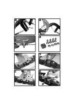
Assembly parts:
1x Drive dog
4x Hexagonal screw M8 x 20
4x Hexagonal nut M8, self-locking
i
Lightly grease the drive dog before
mounting.
27
Align the cutter bar on the blade holder in
the attachment position - align the drive dog
on the centre of the blade holder (turn the
V-belt pulley for this).
28
Lift the scythe mower by the blade holder
so that the drive dog can be inserted into
the guide.
Lower the mower again and insert the
headless screw into the drive dog.
29
Screw the cutter bar and blade holder
together.
30
There must be a gap of approx. 1 mm
between the start of the thread of the
headless screw "
a
" and the drive dog "
b
".
Adjust the headless screw correspondingly.
31
Remove the screw, washers and nut on the
blade holder.
32
Lay the Bowden cable under the protective
cover and then screw the cover back into
place.
Содержание 112 313
Страница 2: ...1 1 1 1 2 2 2 2 1 3 5 2 4 6 8 7...
Страница 3: ...9 11 13 10 12 14a 15a 14b...
Страница 4: ...15b 16 17 20 18 18 24 1 a 19 18 21 22...
Страница 5: ...23 a b 25 24 26 29 28 30 27...
Страница 6: ...32 31...
Страница 31: ...RUS 2 RUS b 16 17 18 19 a c 20 21 22 23 24 25 i 26 1x 4x M8 x 20 4x M8 i 27 28 29 30 a b 1 31 32...
Страница 43: ...Notice...

