background image

Page 11

(Setup Continued)


1.  If further programming is needed, turn system power off, press and hold the “Stream” switch and turn system  


power back on.  Within a few seconds, the LED on the control panel will begin to blink once approximately  


every three seconds.


2.  To program a new deploy position, momentarily press the “Deploy” switch.  The monitor will proceed to the  


default deploy position and stop.  The LED on the control panel will be blinking a code of 1-6 meaning you are  


in deploy setup mode.  After the monitor stops, use right/left/raise/lower controls to position the monitor nozzle  


to the desired deploy position.


3.  When the nozzle is in the desired position, you can save it by pressing either the “Stream” or “Fog” switches.   


If you use the “Stream switch” the nozzle will go to the stream position during deploy.  If you use the “Fog”  


switch, the nozzle will go to the fog position during deploy.


4.  Once the position has been saved, the LED on the control panel will go back to blinking once every three  


seconds.  From this point, you can reset the UII logic box by momentarily pressing the fog switch and it will  


reboot into normal operation mode or continue to step 5 to program the stow position.


5.  To program a new stow position, momentarily press the “Stow” switch.  The monitor will proceed to the default  


stow position and stop.  The LED on the control panel will be blinking a code of 1-5 meaning you are in stow  


setup mode.  Only the nozzle elevation can be set for the stow function.  Use the “Raise” or “Lower” controls to  


move the nozzle to the desired position.


6.  When the nozzle is in the desired position, you can save it by pressing either the “Stream” or “Fog” switches.   


If you use the “Stream switch” the nozzle will go to the stream position during stow.  If you use the “Fog”  


switch, the nozzle will go to the fog position during stow.


7.  Once the position has been saved, the LED on the control panel will go back to blinking once every three  


seconds.  From this point, you can reset the UII logic box by momentarily pressing the fog switch and it will  


reboot into normal operation mode or continue to step 2 below to program the Home position.

POSITION SENSORS

The DeckMaster monitor has been provided with two potentiometers and a Swing Arm Sensor. The two potentiometers 
measure the position of the elevation and rotation.  The “Home” position is set at the factory for the middle of the 
rotation range and coincides with the monitor facing the forward physical position (in line with the vertical groove on 
the outside diameter of the mounting flange).  The home position can be adjusted to allow the monitor to stow at any 
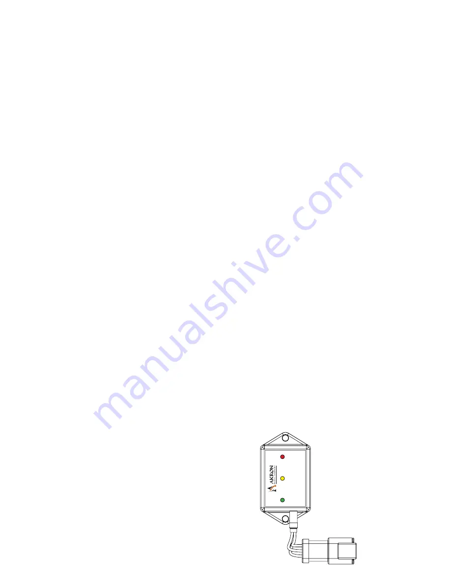
rotational position between the rotational stops.  The Swing Arm Sensor determines which position the Swing Arm 
(center elbows) are in, Stowed, Deployed or somewhere in between.  It puts out a different signal for each of the three 
positions that the logic box uses for proper sequencing and error reporting.  These signals are also visible as different 
colored LED’s on the face of the sensor.  See figure below.

To Adjust the Home Position:
 

1.  Enter the setup mode.  See instructions above for entering the setup mode.


2.  Using the “Stream switch, advance to setup code 2-7.


3.  Operate unit left or right to desired Home position.


4.  Press the “Fog” switch to store the Home position.


5.  Cycle power on to the Universal II Controller.  The monitor will now stow at the new Home position.


RAISED

LOWERED

(Red)

(Yellow) 

(Green)

Swing Arm 

Senser

Содержание DECKMASTER 3440

Страница 1: ...CONFIGURATION WITH POTENTIOMETERS U2 LOGIC BOX INSTALLATION OPERATING AND MAINTENANCE INSTRUCTIONS The following is intended to provide the basic instructions for installation operation and maintenance Read and understand these operation instructions before use ...

Страница 2: ...ation which if not avoided WILL result in death or serious injury Indicates a hazardous situation which if not avoided COULD result in death or serious injury Indicates a potentially hazardous situation which if not avoided may result in minor or moderate injury Addresses practice not related to personal injury Product Warnings Cautions and Notices Use only for firefighting by trained operators Ch...

Страница 3: ...o the Stow position after use If not equipped with an automatic drain valve drain the monitor after use to prevent freeze damage The monitor nozzle logic box control box tether controller and field adjustable stops are made for optimal performance Do not alter in any manner The monitor was designed for use with the 5177Akromatic 1577 SaberMaster or 2499 Stack Tip nozzles Use of any other nozzle co...

Страница 4: ...5 16 16 5 8 14 11 32 4 7 16 18 25 32 19 5 32 17 1 32 27 23 32 4 7 16 5 5 16 11 9 32 16 5 8 18 25 32 23 9 32 DECKMASTER WITH 5177 AKROMATIC NOZZLE 45 225 DEPLOYED LEFT SIDE VIEW DEPLOYED TOP VIEW 170 170 STOWED TOP VIEW NOZZLE AT 90 STOWED LEFT SIDE VIEW NOZZLE AT 90 STOWED TOP VIEW NOZZLE AT 0 ...

Страница 5: ...5 8 4 7 16 18 27 32 18 11 32 19 1 4 11 9 32 14 3 8 4 7 16 29 1 32 24 9 16 18 25 32 5 5 16 16 5 8 11 9 32 DECKMASTER WITH 1578 SABERMASTER NOZZLE 45 225 DEPLOYED LEFT SIDE VIEW DEPLOYED TOP VIEW 170 170 STOWED TOP VIEW NOZZLE AT 90 STOWED LEFT SIDE VIEW NOZZLE AT 90 STOWED TOP VIEW NOZZLE AT 0 ...

Страница 6: ...at the final torque Rotational Hard Stops The stainless steel rotational hard stops set the boundaries for the area that the monitor is allowed to travel left counterclockwise and right clockwise The stop in the lower row controls the left CWW travel and the stop in the upper row controls the right CW travel Refer to figure 3 for the locations of the upper row and the lower row as well as points 1...

Страница 7: ...Page 7 FIGURE 4 Boundary Areas Set by Rotational Hard Stops ...

Страница 8: ... Vehicle Battery 12 24 VDC Red 12 AWG 2 Power In Vehicle Battery Black 12 AWG 3 Power In Auxiliary Battery 12 24 VDC Optional Green 12 AWG 4 Power In Auxiliary Battery Optional Black 12 AWG 5 Output H Bridge 5A Red 16 AWG 6 Output H Bridge 5B Black 16 AWG 7 Output Logic 1 Panel LED Brown 16 AWG 8 Output Logic 2 Discharge Red 16 AWG 9 Output Logic 3 Orange 16 AWG 10 Output Bi stable Relay Common Ye...

Страница 9: ...rn Motor Fog N Blue Black Output Swing Arm Motor Deploy P Black White Output Swing Arm Motor Stow Table 2 Monitor Harness Connections 3440 DeckMaster with UII control Initial setup The following functions can be configured in the setup mode Monitor Orientation sideways or inverted mounting Restore Factory Defaults Obstacle Avoidance Electric Riser Disable Enable Stow and Deploy Positions To enter ...

Страница 10: ...etup 0 1 One slow blink Programming Order See Notes Right Soft Limit 1 1 NOTE 2 Left Soft Limit 1 2 NOTE 2 Up Soft Limit 1 3 NOTE 2 Down Soft Limit 1 4 NOTE 2 Stow 1 5 NOTE 4 Deploy 1 6 NOTE 4 Monitor Orientation 1 7 Zero Position Sensors 1 8 NOTE 1 Restore Factory defaults 1 9 Obstacle avoidance Disable 2 1 Obstacle Avoidance Manual Operation 2 2 NOTE 3 Obstacle Avoidance Auto Operation 2 3 NOTE ...

Страница 11: ... it by pressing either the Stream or Fog switches If you use the Stream switch the nozzle will go to the stream position during stow If you use the Fog switch the nozzle will go to the fog position during stow 7 Once the position has been saved the LED on the control panel will go back to blinking once every three seconds From this point you can reset the UII logic box by momentarily pressing the ...

Страница 12: ...troller until the desired position is reached 9 To change the nozzle pattern toward the straight stream or fog position 10 Press the proper toggle switch toward STRAIGHT or FOG respectively as labeled on the controller until the desired nozzle position is reached B MANUAL OVERRIDE CONTROLS The manual override control is to be used only when the power to the monitor is off A single override crank w...

Страница 13: ...o overhaul the joint to clean and replace the grease See Table 1 and Table 2 below for grease volumes Periodically inspect the condition of the grease in the elevation and rotation joints See the tables below for recommendations regarding the condition of the grease Do not apply grease more frequently than 1 time per month Standard recommended grease is Lubriplate Low Temp This is an anhydrous cal...

Страница 14: ...y revised 05 18 ISO 9001 REGISTERED COMPANY ERROR CODES Error Codes consist of a two part blink code The first digit can be 1 2 or 3 short blinks followed by another set of short blinks 1 9 On the last blink of the second digit the LED remains on so it appears to be a long blink then the code repeats itself For example error code 1 1 appears visually as a short blink short pause with LED off then ...

Отзывы: