– 32 –
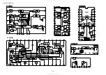
<CD>
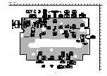
CD C.B
CN401
SFR430
TP
(VREF)
IC404
CN405
CN403
IC402
IC401
41
TP(RFSM)
TP(TE)
R405
C431
+
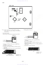
Note: • Connect a provbe (10 : 1) of the oscilloscope to adjust.
• Connect negative side of the oscilloscope to TP (VREF) for
each adjustment.
1. Focus Bias Adjustment
Adjust focus bias when replaing or repairing the optical block.
2. Tracking Balance Adjustment
1) Connect an oscilloscope to the test point TP (TE) and
TP (VREF).
2) Active the CD test mode.
3) Insert the test disc TCD-782 (YEDS-18) and choose traverse
mode of CD test mode.
4) Check that the waveform of traverse is vertically symmetrical as
shown below.
5) Cancel CD test mode after checking.
+
_
Oscilloscope
(DC range)
TP (RFSM)
TP (VREF)
+
_
Oscilloscope
(DC range)
TP (TE)
TP (VREF)
EYE PATTERN
must be CLEAR and MAX
Max
VOLT/DIV: 0.5V
TIME/DIV: 0.5uS
A
B
VOLT/DIV: 20mV
TIME/DIV: 1mS
A=B
VREF
www. xiaoyu163. com
QQ 376315150
9
9
2
8
9
4
2
9
8
TEL 13942296513
9
9
2
8
9
4
2
9
8
0
5
1
5
1
3
6
7
3
Q
Q
TEL 13942296513 QQ 376315150 892498299
TEL 13942296513 QQ 376315150 892498299

