– 28 –
ADJUSTMENT
1. Adjustment Mode
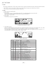
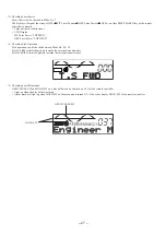
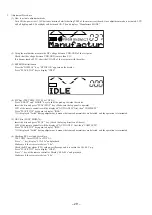
Operations in Adjustment Mode can be checked on the LCD of the remote controller.
GND
TEST
VDD
ADJ
RF
VO
VC
MAIN circuit board Test Points
(1) Preparation
Disc to be used
• PIT disc (pre-mastered disc): TEST DISC (TGYS1 or TDYS-1)
• GRV disc (MO disc): SONY MDW-74 (fully recorded)
Measuring device
• Digital Multimeter
• Direct current regulation power supply (REGULATED DC POWER SUPPLY)
• Oscilloscope
(2) Note
• If a disc had any stains or scars on, the adjustment may not be completed.
• Always place the main unit with its cassette cover upward for adjustment.
• Do not make any manual adjustment.
• If the adjustment is incomplete, it displays “NO ADJ” during normal operation.
(3) Prohibitions
Do not press DSL key of the remote controller. If it was pressed, the mode will change to factory shipment mode.
If any data is changed in this mode, the unit will not be able to function normally.
If accidentally change into this mode, initialize EEPROM and re-do all the adjustments.
Содержание AM-HX100
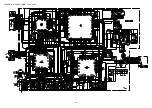
Страница 14: ... 14 SCHEMATIC DIAGRAM MAIN FLEX JACK ...
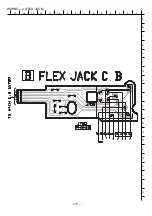
Страница 15: ...WIRING 2 FLEX JACK 15 14 13 12 11 10 9 8 7 6 5 4 3 2 1 A B C D E F G H I J K L M N O P Q R S T U 15 ...
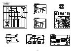
Страница 16: ... 16 IC BLOCK DIAGRAM ...
Страница 34: ...2 11 IKENOHATA 1 CHOME TAITO KU TOKYO 110 JAPAN TEL 03 3827 3111 Printed in Singapore 2000068 921338 ...
Страница 48: ... 14 SCHEMATIC DIAGRAM 1 MAIN ...
Страница 49: ...2 11 IKENOHATA 1 CHOME TAITO KU TOKYO 110 JAPAN TEL 03 3827 3111 Printed in Singapore 9820543 ...

