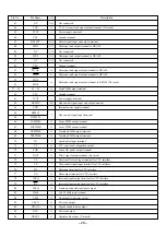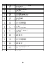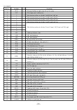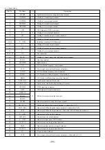
25
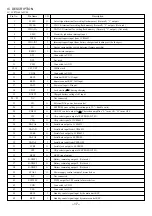
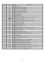
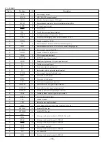
Pin No.
Pin Name
I/O
Description
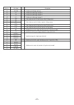
45
SLPWM
I
Sled motor PWM input terminal.
46
S3
I
Sled motor decoder input terminal 3.
47
S2
I
Sled motor decoder input terminal 2.
48
S1
I
Sled motor decoder input terminal 1.
49
CP2
Connecting terminal to 2nd phase capacitor of charge pump.
50
CP1
Connecting terminal to 1st phase capacitor of charge pump.
51
CPC1
52
CPC2
Connecting terminal to 2nd phase capacitor of charge pump.
53
CPO
Connecting terminal to last phase capacitor of charge pump.
54
RF1
I
Spindle motor electric current detection terminal. (Connected to GND)
55, 59
VS
Spindle motor drive power supply terminal. (Connected to VM)
56
SPWOUT
57
SPVOUT
O
Spindle motor power supply output terminal.
58
SPUOUT
60
RF2
I
Spindle motor electric current detection terminal. (Connected to GND)
61
SPUCIN
62
SPVCIN
I
Spindle motor counter electromotive voltage detection terminal.
63
SPWCIN
64
SPCOMIN
Содержание AM-HX100
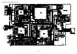
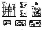
Страница 14: ... 14 SCHEMATIC DIAGRAM MAIN FLEX JACK ...
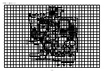
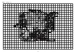
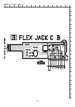
Страница 15: ...WIRING 2 FLEX JACK 15 14 13 12 11 10 9 8 7 6 5 4 3 2 1 A B C D E F G H I J K L M N O P Q R S T U 15 ...
Страница 16: ... 16 IC BLOCK DIAGRAM ...
Страница 34: ...2 11 IKENOHATA 1 CHOME TAITO KU TOKYO 110 JAPAN TEL 03 3827 3111 Printed in Singapore 2000068 921338 ...
Страница 48: ... 14 SCHEMATIC DIAGRAM 1 MAIN ...
Страница 49: ...2 11 IKENOHATA 1 CHOME TAITO KU TOKYO 110 JAPAN TEL 03 3827 3111 Printed in Singapore 9820543 ...


