4
DISASSEMBLY INSTRUCTIONS
a
a
a
a
a
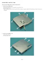
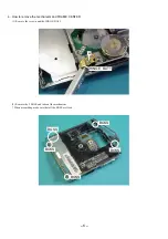
Removing only the PANEL, BOT can make the service position.
1. How to remove PANEL, BOT
(1) Remove the 5 screws a1-a5 (1.4-1.8) and the 2 screws b1,b2 (1.4-1.4).
(2) Take out PANEL, BOT.
* When assembling, put the PANEL, BOT from HP JACK side with care for strap hole and HOLD SW. Install the screws from 1 to 5 as shown in
the diagram.
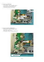
2. How to remove PANEL, TOP
(1) Remove the 5 screws (a).
(2) Remove PANEL, TOP.
b2
a2
a1
a5
a4
a3
b1
Содержание AM-HX100
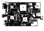
Страница 14: ... 14 SCHEMATIC DIAGRAM MAIN FLEX JACK ...
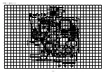
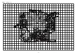
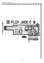
Страница 15: ...WIRING 2 FLEX JACK 15 14 13 12 11 10 9 8 7 6 5 4 3 2 1 A B C D E F G H I J K L M N O P Q R S T U 15 ...
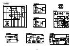
Страница 16: ... 16 IC BLOCK DIAGRAM ...
Страница 34: ...2 11 IKENOHATA 1 CHOME TAITO KU TOKYO 110 JAPAN TEL 03 3827 3111 Printed in Singapore 2000068 921338 ...
Страница 48: ... 14 SCHEMATIC DIAGRAM 1 MAIN ...
Страница 49: ...2 11 IKENOHATA 1 CHOME TAITO KU TOKYO 110 JAPAN TEL 03 3827 3111 Printed in Singapore 9820543 ...


