background image

11

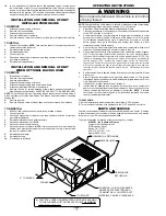
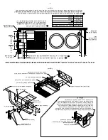
Pour le nettoyage de la chambre de combustion, on doit retirer l'appareil de la caissee, et 

retirer également le ventilateur et les organes de commande; il ne doit rester que la 

chambre de combustion, comme on le voit sur l'illustration. Injecter de l'air comprimé dans 

la chambre selon les indications des fleches pour expulser la suite et les débris.

Figure 8

Figure 9

INCORRECT

INCORRECT

CORRECT

Figure 10

Содержание Suburban SF Series

Страница 1: ...ctric generator Contact the nearest gas supplier or qualified service technician for repairs If you cannot reach a gas supplier or qualified service technician contact the nearest fire department Do n...

Страница 2: ...t be installed on vinyl siding without first consulting with the manufacturer of the siding or cutting the siding away from the area around the appliance vent In any installation in which the vent of...

Страница 3: ...ied by installer Maximum wall thickness for this type installation is 2 1 Locate the furnace near lengthwise center of the coach 2 Choose a location for installation out of the way of wires pipes etc...

Страница 4: ...essure equal to or less than 1 2 PSIG 1 A 3 8 male flare connection is provided for gas line hookup Some standards may require the use of a manual shut off valve in the gas line external to the furnac...

Страница 5: ...f intake combustion air and the flow of exhaust gases being expelled to the outside atmosphere not be obstructed Any soot or loose debris should be blown out using compressed air See Figure 8 6 Inspec...

Страница 6: ...alve at the outside Propane tank to the OFF position Do not force 3 Set thermostat above room temperature to begin blower operation A slight delay will occur before the blower comes on Allow blower to...

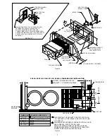
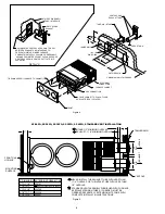
Страница 7: ...L 2 2 3 4 DIA HOLES CL X INTAKE 1 2 MINIMUM OVERLAP EXHAUST 1 1 4 MINIMUM OVERLAP 2 3 4 DIA 2 3 4 DIA C L L C EXHAUST INTAKE 0 TO 1 1 2 520768 520968 520551 TRAILER SKIN VENT CAP MOUNTING SURFACE NEVE...

Страница 8: ...IS ESSENTIAL DETAIL A VENT CAP AND EXHAUST TUBE INTAKE AIR OUTSIDE SKIN PANEL SF 20FQ SF 25FQ SF 30FQ SF 35FQ SF 42FQ STANDARD VENT INSTALLATION X INTAKE 1 2 MINIMUM OVERLAP EXHAUST 1 1 4 MINIMUM OVE...

Страница 9: ...GE OF THE FRAME DOOR FRAME INTAKE TUBE 6 SCREWS SUPPLIED VENT CAP EXHAUST TUBE 4 SCREWS DOOR MOUNTING FURNACE ACCESS DOOR SECURE FRAME TO OUTER PANEL WITH SCREWS 16 PLACES GAS CONNECTION ELECTRICAL CO...

Страница 10: ...ITH WIRING MATERIAL HAVING A TEMPERATURE RATING OF AT LEAST 105 C CAUTION DO NOT HI POT DIELECTRIC HIGH VOLTAGE TEST THIS UNIT AFTER INSTALLATION TO DO SO MAY CAUSE COMPONENT DAMAGE AND VOIDS WARRANTY...

Страница 11: ...11 Figure 9 INCORRECT INCORRECT CORRECT Figure 10...

Страница 12: ...TIES INCLUDING IMPLIED WARRANTIES OF MERCHANTABILITY ARE HEREBY LIMITED IN DURATION TO THE PERIOD FOR WHICH EACH LIMITED WARRANTY IS GIVEN SOME STATES DO NOT ALLOW LIMITATIONS ON HOW LONG AN IMPLIED W...

Страница 13: ...iqu es pour la garantie de deux ann es L EXCEPTION que Suburban ne remboursera aucun frais de main d oeuvre LIMITATION DES GARANTIES LA P RIODE DE VALIDIT DES GARANTIES IMPLICITES CECI INCLUANT LES GA...

Страница 14: ...alement le ventilateur et les organes de commande il ne doit rester que la chambre de combustion comme on le voit sur l illustration Injecter de l air comprim dans la chambre selon les indications des...

Страница 15: ...EURS NOTE S IL EST NECESSAIRE DE REMPLACER CERTAINS CALIBRE 18 POUR TOUS LES CONDUCTEURS SAUF D AU MOINS 105 C INDICATION DIFFERENTE Figure 7 2 M A X C L 9 7 6 4 1 8 3 2 7 8 9 3 2 TUBE D ADMISSION D A...

Страница 16: ...TUBE D ADMISSION D AIR BOUCHES D ADMISSION D AIR D CHARGE AVEC TUBE DE D CHARGE PANNEAU EXTERNE Figure 4 SF 20FQ SF 25FQ SF 30FQ SF 35FQ SF 42FQ INSTALLATION STANDARD DU SYST ME D ARRIV E ET DE D CHA...

Страница 17: ...BOUCHE D ADMISSION D AIR D CHARGE PANNEAU EXTERNE L C Figure 2 X ARRIVE 1 2 POUNCE MINIMUM DE CHEVAUCHEMENT D CHARGE 1 1 4 POUNCES MINIMIMUM DE CHEVAUCHEMENT 2 3 4 DIA 2 3 4 DIA C L L C D CHARGE ARRIV...

Страница 18: ...rrupteur d arr t est en position ON pour un fonctionnement correct 6 R gler le thermostat pour la temp rature d sir e Si cette temp rature est sup rieure celle de la pi ce le ventilateur se met en mar...

Страница 19: ...ais tenter de r parer l appareil de chauffage Confier ces travaux un technicien comp tent 12 Ne jamais r duire la taille des conduits install s par le constructeur du v hicule Ceci susciterait un fonc...

Страница 20: ...it traverse une paroi de mat riaux combustibles comme la paroi d un placard du v hicule maintenir un espacement d au moins 1 4 po voir Figure 3 REMARQUE L espacement peut tre nul dans le cas de condui...

Страница 21: ...ouclier anti pluie fourni voir figure 1 d tail A Ne pas modifier le syst me d vacuation fourni avec cet appareil de chauffage Toute modification provoquera une d ficience de l installation pouvant sus...

Страница 22: ...etc qui pourrait interf rer avec l installation Respectez les distances minimales entre l armoire et la construction combustible indiqu es dans le tableau 2 Reportez vous la figure 1 pour voir les d g...

Страница 23: ...u e lors de l ouverture d une porte du v hicule Si ceci n est pas possible on doit limiter le mouvement d ouverture de la porte afin qu il y ait un espacement libre de s curit d au moins 6 po entre la...

Страница 24: ...aves ou la mort Suivre les instructions et les consignes qui figurent dans la notice d utilisation qui accompagne ce g n rateur d air chaud L installation et l entretien doivent tre effectur s par un...

Отзывы: