IOM-PreciseAIR
Page
32
of
50
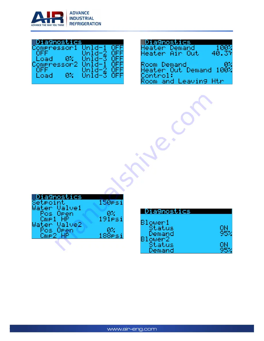
Each compressor state (ON or OFF) and its
calculated load in %. It also displays the state (ON
or OFF) for each unloader (Unld).
The number of unloaders varies with the model
number. If the compressor is ON and all
unloaders are OFF it means that the compressor
is fully loaded (100%) and delivering maximum
cooling capacity to the system. If one or more
unloaders are ON, the compressor is in an
unloaded state and the load % is less than 100%.
It value depends on the number of unloaders
that are ON. If all unloaders are ON, the
compressor delivers 0% of its maximum cooling
capacity, therefore running fully unloaded.
The compressors and unloaders states (ON or
OFF) are based on the System Demand %.
Only applicable to water cooled units. It displays
the compressor high pressure (HP) setpoint, the
current value for each compressor HP and the
current open position of the respective water
valve. The controller opens the valve to lower
the HP and closes the valve to increase the HP.
When heaters are available, this screen displays
the heaters variables. Heater demand is the
power % applied to the heater through a 0-
10VDC signal to the heaters SCR’s.
Heater Demand assumes the highest value
between Room Demand and Heater Out
Demand.
Control displays which demands are being
considered for Heater Demand. On this example,
both Room Demand (Room) and Heater Out
Demand (Leaving Htr) are being considered. The
control can be changed to only one Demand.
Heater Air Out is the temperature of the air
leaving the heaters. When the Heater Demand is
higher than 0% this temperature should be
higher than the temperature entering the heater
(which is the same as the temperature leaving
the cooling coil - Evap Air Out).
It displays the Blowers status (ON or OFF) and
the demand in %. The demand is the same as the
% of the maximum speed configured for the
blower in the VFD. In this example, if the
maximum speed is set to 1800 RPM at 60Hz, 95%
corresponds to a VFD output of 57Hz and 1,710
RPM.
Содержание PreciseAIR PCA Series
Страница 15: ...IOM PreciseAIR Page 15 of 50 2 13 Main Control Panel Layout and Components Figure 4 Main Control Panel Layout...
Страница 27: ...IOM PreciseAIR Page 27 of 50 3 6 Setpoint Screens...
Страница 28: ...IOM PreciseAIR Page 28 of 50...
Страница 49: ...IOM PreciseAIR Page 49 of 50 4 11 Maintenance Logs...


