MN-745
6
GETTING STARTED
1. Raise the vehicle up with a hoist or jack up the rear with a jack. Place Jack stands under
the axle and lower the vehicle down if using a frame contact hoist (so vehicle is at curb
height).
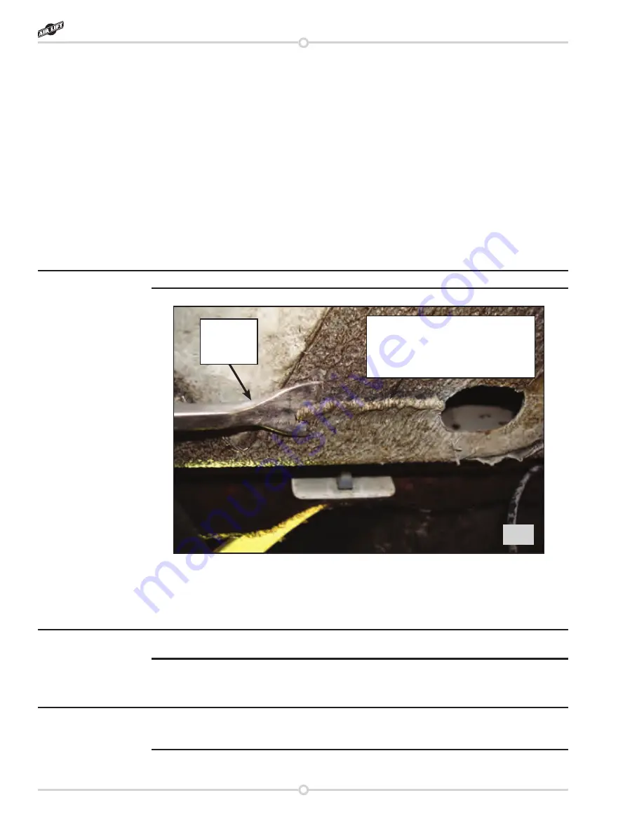
2. The air spring assembly fits forward of the axle. On some models there is a thick coat
of a body filler type substance that will need to be removed where the upper bracket
contacts the frame (fig. 6). Set the left and right hand assembly in place on the axle,
make sure the “finger” of the lower bracket is over the leaf spring U-bolt. Align the spring
so it is perpendicular to both upper and lower brackets. Mark the frame in the area that
the upper bracket makes contact with the frame and remove both assemblies. This is
the area that you will need to remove the “body filler” material so that the bracket fits flat
to the frame. Use a gasket scraper or a chisel to remove the material.
I use an air chisel with light pressure to remove the material.
3. Set the assemblies back in place forward of the axle with the holes in the upper bracket
pointing inboard.
4. With the finger of the lower bracket over the stock U-bolt, attach it to the leaf spring with
the U-bolt (H), clamp bar (G), flat washers (K) and nyloc nuts (J) (fig. 7).
Offset the lower bracket to the inside of the vehicle on the leaf spring before tightening
hardware. Torque to 16ftlbs and repeat for the opposite side.
5. With the lower bracket attached to the leaf spring, align the upper bracket on the frame
so that the air spring is perpendicular to both the upper and lower bracket (fig. 8). Keep
the bracket centered on the frame, between the outside and inside while positioning.
It may be helpful to have slight pressure in the air spring for aligning and attaching the upper
bracket to the frame. Cut the air line (L) in two equal lengths (see hose attaching instructions)
and insert the air line into the air spring fittings. Inflate the springs to 5psi (or less).
6. Using the upper bracket as a template, drill two ¼” holes through the bottom of the frame
(fig. 8).
Installing the RideControl System
fig. 6
Bead of “body filler” type substance
that will need to be removed so
that the upper bracket will fit flush
to the frame
Scrapper
removing
bead
NOTE
NOTE
NOTE
RideControl


