background image

Air Lift 1000

MN-34

7

5. Push the inflation valve through the hole and use the rubber washer, flat washer, and

another 5/16” nut to secure it in place. Tighten the nuts to secure the assembly.

6. Route the air line along the frame to the fitting on the air spring (Fig. D.3). Keep

AT LEAST 6” of clearance between the air line and the exhaust system. Avoid sharp
bends and edges. Use plastic tie straps to secure the air line to fixed points along the
chassis. Be sure that the tie straps are tight, but do not pinch the air line. Leave at least 2”
of slack to allow for any movement that might pull on the air line.

7. Cut off the air line, leaving approximately 12” of extra air line. A clean square cut will

prevent leaks. Insert the air line into the air fitting. This is a push-to-connect fitting.
Simply push the air line into the 90° swivel fitting until it bottoms out (9/16” of air line
should be in the fitting).

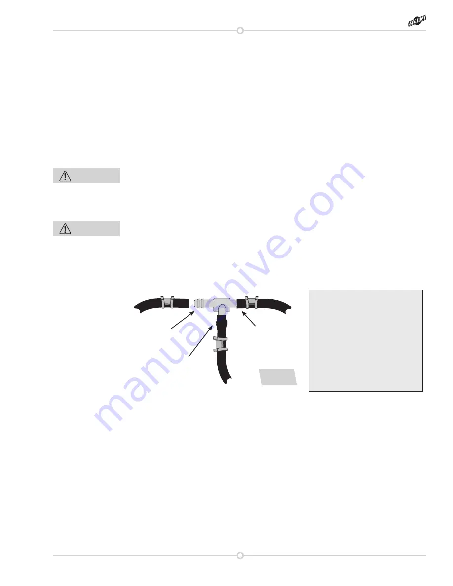
TEE AIR LINE ROUTING

TO PREVENT THE AIR LINE FROM MELTING, MAINTAIN AT LEAST 8” FROM THE 
EXHAUST SYSTEM TO THE AIR LINE.

1. Locate the desired tee location on the frame rail or cross member. Determine and

cut an adequate length of air line to reach from the tee to the left and right side air

springs.

LEAVE SUFFICIENT AIR LINE SLACK TO PREVENT ANY STRAIN ON THE FITTING 
DURING AXLE MOTIONS.

2. Slide an air line clamp onto the air line.
3. Push the air line over one side of the tee until all the barbs are covered. With a pair of

pliers, slide the air line clamp forward until it fully covers the barbed section. Repeat

the entire procedure for the other leg of the tee. (Fig. D.3)

4. Route the air line along the cross member and either the lower control arm or the

upper spring seat to the air spring.

5. Insert the air line through the spring seat and spacers.
6. Push the air line onto the stem, covering all the barbs. With the pliers, slide the air line

clamp upward until it fully covers the barbed section.

Use this procedure for all air 

line connections:

1. Slide the air line clamp onto

the air line.

2. Push the air line over the

barbed stem.

3. Compress the ears on the

air line clamp with pliers and

slide it forward to fully cover

the barbed section.

1

2

3

fig. D.3

CAUTION

CAUTION

Содержание Air Lift 1000 60713

Страница 1: ...veness and safety please read these instructions completely before proceeding with installation Failure to read these instructions can result in an incorrect installation Kit 60713 MN 34 111604 ECR 8475 INSTALLATION GUIDE ...

Страница 2: ...s 6 Tee Air Line Routing 7 Completing the Installation 8 Installing the Heat Shield 8 E Before Operating 8 Installation Checklist 9 Post installation checklist 9 F Product Use Maintenance and Servicing 10 Suggested Driving Pressure and Maximum Air Pressure 10 Operating Tips 10 Tuning the Air Pressure 11 Guidelines for Adding Air 11 G Troubleshooting Guide 12 Frequently Asked Questions 12 Limited W...

Страница 3: ...pressure data is shown on the vehicle s Safety Compliance Certification Label Payload The combined maximum allowable weight of cargo and passengers that the vehicle is designed to carry Payload is GVWR minus the Base Curb Weight NOTATION EXPLANATION Hazard notations appear in various locations in this publication Information which is highlighted by one of these notations must be observed to help m...

Страница 4: ...ir Lift 1000 System GETTING STARTED 1 Jack up the rear of the vehicle or raise on a hoist Support the frame with safety stands 2 Mark the location of the spring upper spring mount with a marker so that the spring can be reinstalled and indexed properly 3 Remove the shock absorbers from the lower shock mounts on the axle Lower the axle or raise the body of the vehicle until the springs can be remov...

Страница 5: ...der assembly on the control arm lower seat 3 Mark the cylinder air stem location where it comes in contact with the control arm 4 Remove coil spring and air spring assembly 5 Center punch and drill 1 4 diameter pilot hole then drill 3 8 diameter final hole to allow attachment of the air line to the air cylinder Fig C 3 fig C 2 fig C 3 Control arm 4 ...

Страница 6: ... Raise axle back to starting position Re attach the shock and torque to manufacturer s specification 14 Move the left jack stand under axle and the right jack stand under frame and repeat steps 4 through 13 to install the right side Check exhaust clearance There must be 3 4 inches between the air bag and the exhaust or the heat from the exhaust could damage it If there is insufficient clearance co...

Страница 7: ...se plate recess in bumper c Under the gas cap access door d Through the license plate Whatever the chosen location make sure there is enough clearance around the inflation valves for an air chuck 2 Drill 5 16 holes to install the inflation valves 3 If installing dual air lines cut the air line assembly in two equal lengths 4 Place a 5 16 nut and star washer on the air valve Leave enough of the inf...

Страница 8: ...E EXHAUST SYSTEM TO THE AIR LINE 1 Locate the desired tee location on the frame rail or cross member Determine and cut an adequate length of air line to reach from the tee to the left and right side air springs LEAVE SUFFICIENT AIR LINE SLACK TO PREVENT ANY STRAIN ON THE FITTING DURING AXLE MOTIONS 2 Slide an air line clamp onto the air line 3 Push the air line over one side of the tee until all t...

Страница 9: ...ar against the fitting and pulling firmly on the air line Trim 1 off the end of the air line Be sure the cut is clean and square see Fig b Reinsert the air line into the push to connect fitting b Check the threaded connection by tightening the swivel fitting another half turn If it still leaks deflate the air spring remove the fitting and re coat the threads with thread sealant Reinstall by hand t...

Страница 10: ...that might rub against them Be sure to check the tire brake drum frame shock absorbers and brake cables Leak test before road test Inflate the air springs to 30 PSI check all connections for leaks with a soapy water solution See Checking for Leaks on how to spot leaks All leaks must be eliminated before the vehicle is road tested Heat test Be sure there is sufficient clearance from any heat source...

Страница 11: ...AT A MAXIMUM INFLATION PRESSURE OF 35 PSI OR 50 PSI THE AIR PRESSURE ACTUALLY NEEDED IS DEPENDENT ON LOAD AND GVWR 5 If using Schrader valves always add air to the springs in small quantities checking the pressure frequently Cylinders require less air volume than a tire and inflate quickly 6 Should it become necessary to raise the vehicle by the frame make sure the system is at a minimum pressure ...

Страница 12: ...ude roll control bounce dive during braking and sponginess Fig F 3 Tuning out these problems usually requires an increase in pressure GUIDELINES FOR ADDING AIR 1 Start with the vehicle level or slightly above 2 When in doubt always add air 3 If the front of the vehicle dives while braking increase the pressure in the front air bags if equipped 4 If it is ever suspected that the air bags have botto...

Страница 13: ...s will not change the weight ratings GAWR GCWR and or GVWR of a vehicle Exceeding the GVWR is dangerous and voids the Air Lift warranty Q Is it necessary to keep air in the air springs at all times and how much pressure will they need The recommended minimum air pressure for the Air Lift 1000 kit is 5 PSI Q Is it necessary to add a compressor system to the air springs No Air pressure can be adjust...

Отзывы: