Analysis shows that steam pressure must be reduced dramatically to achieve a slight
lowering of temperature. In most applications this can result is sub-atmospheric
pressure in the coil, while as much as 75% of full condensate load has to be handled
by the steam trap. This is especially important for coils exposed to outside air, since
sub-atmospheric conditions can occur in the coil at outside temperatures below 32
o
F
(0
o
C) and the coil will freeze if the condensate is not removed. There are detailed
methods for determining condensate load under various operating conditions.
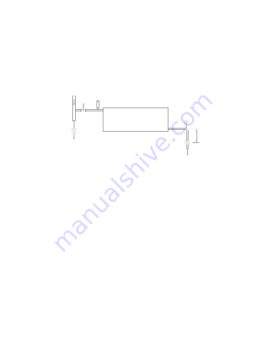
However, on most cases, this load does not need to be calculated if the coils are piped
as shown in the figure below and this procedure is followed.
breaker
Vacuum
Regulating
valve
Condensate
Trap
Supply
To atmoshperic drain or receiver,
COIL
Trap
Air purge
min.
300
Do not lift except by pump.
The steam trap should be 1 to 3ft (0.3 to 0.9m) below the bottom of the steam coil to
provide a hydraulic head of approximately 0.5 to 1.5 psig (3.5 to 10.3kpa above atm.).
Location of the trap at less than 12in (300mm) minimum usually results in improper
drainage and operating difficulties.
Vacuum breakers must be installed between the coil and the trap inlet to
ensure that the hydraulic head drain the coil when it is at atmospheric or sub-
atmospheric pressure. The vacuum breaker should respond to a differential
pressure of no greater than 3in. of water (750pa). For atmospheric returns, the
vacuum breaker should be opened to the atmosphere, and the return system
must be designed to ensure no pressurization of the return line. In vacuum
return systems, the vacuum breaker should be piped to the return line.
Discharge from the trap must flow by gravity, without any lifts in the piping,
to the return system, which must be vented properly to the atmosphere to
eliminate any back pressure that could prevent the trap from draining the coil.
Where the return main is overhead, the trap discharge should flow by gravity
to a vented receiver, from which it is then pumped to the overhead return.
Traps must be designed to operate at maximum pressure at the control valve
inlet and sized to handle the full condensate load at a pressure differential
equal to the hydraulic head between the trap and coil. Since the actual
condensate load can vary from the theoretical design load because of the
safety factors used in coil selection and the fact that condensate does not
always form at a uniform steady rate, steam traps should be sized according to
the following:-


