background image

7

PART NAMES

INSTALLATION

USING THE SYSTEM

APPENDIX

SETTING AND ADJUSTMENT

Basic connection methods

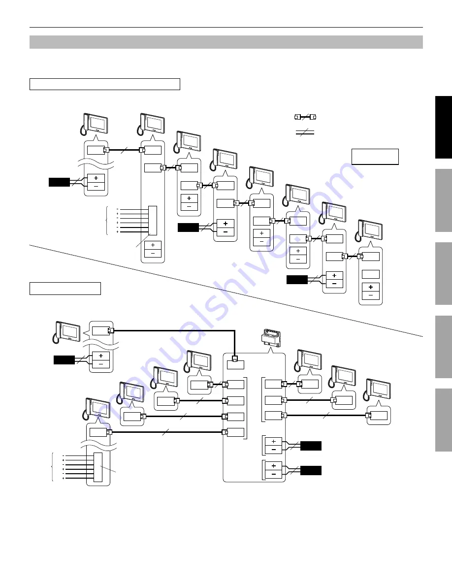
Up to seven sub master stations can be connected to the system. The connecting method for sub master stations differs depending 
on the system connection method, “station-to-station wiring” or “home-run wiring”.

Station-to-station (daisy-chained) wiring

PS24

P

2

PS24

P

2

PS24

P

2

PS24

P

2

PS24

P

2

PS24

P

2

M (IN)

M (IN)

M (IN)

M (IN)

M (OUT)

M (OUT)

M (IN)

M (IN)

M (OUT)

M (OUT)

M (OUT)

M (OUT)

M (IN)

M (OUT)

M (IN)

2

:

:

M (OUT)

M (OUT)

M (IN)

M (OUT)

M (IN)

M (OUT)

M (IN)

M (OUT)

M (IN)

M (OUT)

M (IN)

M (OUT)

M (IN)

M (OUT)

M (IN)

M (OUT)

FS

FS

BP1

BP1

BP2

BP2

FS

FS

BP1

BP1

BP2

BP2

NOTES:

The power supply method shown in the above fi gures is an example.  (

• 


Refer to "Installation manual" for the master station)

Do not use the unused terminals and ports for other purposes.

• 

In order to prevent miswiring, label both ends of each cable with the unit and terminal names to which they are to be connected.

• 

For connecting other manufacturers’ products, refer to the instruction manuals for those products.

• 

The positions of the terminals on the above illustrations differ from the actual product. This is to simplify the diagram.

• 

This unit is not a computer peripheral. Do not connect it to a LAN network.

• 

NP: Non-polarized
P: Polarized

CATe5 (non-shielded)

P. 8

P. 8

6-pin option connector

Home-run wiring

Ø1.0mm, 18AWG 2 conductor cable

Master station
(ID = 1)
JP-4MED

Master station
(ID = 1)
JP-4MED

Sub master station 1 (ID = 2)
JP-4HD

Sub master station 2 (ID = 3)
JP-4HD

Sub master station 3 (ID = 4)
JP-4HD

Sub master station 4 (ID = 5)
JP-4HD

Sub master station 5 (ID = 6)
JP-4HD

Sub master station 6 (ID = 7)
JP-4HD

Sub master station 7 (ID = 8)
JP-4HD

Distribution adaptor
JP-8Z

Sub master station 1 

(ID = 2)

JP-4HD

Sub master station 2 

(ID = 3)

JP-4HD

Sub master station 3 

(ID = 4)

JP-4HD

Sub master station 4 

(ID = 5)

JP-4HD

Sub master station 5 (ID = 6)
JP-4HD

Sub master station 6 (ID = 7)
JP-4HD

Sub master station 7 

(ID = 8)

JP-4HD

6-pin option connector

to Group 1

to Group 2

Power supply 

for Group 1

DC24V

Power supply 

for Group 2

DC24V

Содержание JP-4HD

Страница 1: ...manual for safe and correct use of the system and keep it in a safe place for future reference Please note that images and illustrations depicted in this manual may differ from the actual product JP 4...

Страница 2: ...5 Setting the PIN GENERAL PIN SETTING 15 Call settings CALL 15 Designate door stations allowed to call in to this station DOOR STATION SETTINGS 15 Designate residential station s that receive a call f...

Страница 3: ...CALLING MONITORING OTHER STATIONS 23 Calling all residential stations simultaneously 23 Calling another residential station 23 Monitoring 24 Monitoring door station entrance 24 Monitoring residential...

Страница 4: ...or unit trouble could result Places under direct sunlight or near heating equipment that varies in temperature Places subject to dust oil chemicals hydrogen sulfide hot spring Places subject to moist...

Страница 5: ...image but this is not a malfunction Normal operation will be restored when moisture evaporates 26 When the unit s screen is illuminated with strong light the image looks white or silhouetted but this...

Страница 6: ...o not bend the cables to an extent where the radius is less than 25 mm 1 Communication failure could result Do not remove the CAT5e cable jacket more than necessary This unit is not a computer periphe...

Страница 7: ...ich they are to be connected For connecting other manufacturers products refer to the instruction manuals for those products The positions of the terminals on the above illustrations differ from the a...

Страница 8: ...terminals Less than 5 V DC when open between terminals 2 3 External door release input 1 2 Connect a door release button to each pair of these inputs Input method N O or N C dry closure contact start...

Страница 9: ...e the cover and then slide it to the left until it clicks Make sure the cover is locked Surface wiring When the wiring is not coming through the wall the cable and wires can be routed through the top...

Страница 10: ...p has been performed the display returns to HOME window A notice message is displayed You can release the HOME button Touch 3 ENTER to continue The INSTALL menu window is displayed Program the setting...

Страница 11: ...until 2 highlighted Touch 3 ENTER to save ID When ID is changed this station will be rebooted Initializing station INITIALIZE By initializing this station all settings return to default From th 1 e IN...

Страница 12: ...lue Blinking every 0 5 seconds Rebooting Handset Color LCD touchscreen See the next page for details Status LED Indicates current status of this station by lighting up or blinking See the table below...

Страница 13: ...ation or another residential station SETTINGS P 14 Touch this to program settings and adjustments OFF Touch this to turn screen off and set this station in standby mode OPTION P 26 Touch this to activ...

Страница 14: ...SETTINGS 1 DOOR1 DOOR2 DOOR3 DOOR4 ENABLE DISABLE ENABLE for each ROOM STATION CALL SETTINGS 1 ID1 ID2 ID3 ID4 ID5 ID6 ID7 ID8 The ID number of this station is not displayed ENABLE DISABLE ENABLE for...

Страница 15: ...ou must keep the PIN without fail If you forget the PIN you must initialize this station by the INSTALL menu thus all the setting contents return to default Call settings CALL You can make the followi...

Страница 16: ...ws the station to receive a call from this station DISABLE Does not allow the station to receive a call from this station Repeat for other stations 4 Use or to scroll between ID numbers When the setti...

Страница 17: ...t and disabled From HOME window touch 1 SETTINGS GENERAL DOOR RELEASE Enter the 4 digit PIN by using the touchscreen then 2 touch ENTER DOOR1 to DOOR4 are displayed If a wrong PIN has been entered an...

Страница 18: ...t Communication also ends automatically after 1 minute in hands free mode or after 3 minutes using handset NOTE If this station is not set to receive a call from a specific door station there will be...

Страница 19: ...ng becomes enabled automatically Communication ends automatically after approx 10 minutes The ID number of the calling station will not be displayed If another residential station is calling all the o...

Страница 20: ...Touch 2 or to change the level Adjusting viewability of images ADJUST If the image on the screen is hard to see due to bright light adjust settings NOTE This function is not available for an image fr...

Страница 21: ...d on the screen If is grayed out disabled check DOOR RELEASE and change if needed P 17 It may not be possible to enable at DOOR RELEASE if it is set to be disabled by the INSTALL menu on the master st...

Страница 22: ...tween you and the door station ends When someone touches 5 TALK or lifts handset on the target station he or she can talk with the door station side If handset is lifted in step 3 hang up once and the...

Страница 23: ...m the target stations cannot be heard If someone touches 5 TALK or lifts handset at one of the target stations communication between this station and the target station is initiated To complete commun...

Страница 24: ...n is automatically activated on door station depending on settings Monitoring residential station Audio only You can monitor sounds at another residential station Press the HOME button touch screen or...

Страница 25: ...ID number is shown the status LED blinks in red and an alarm sounds on all the residential stations NOTES The alarm sounds in the maximum volume 10 even if the volume of call tone is set to 0 Door st...

Страница 26: ...This is available when one or two door release buttons are connected to the external door release inputs 1 and or 2 of this station The door at the door station 1 or 2 or both doors can be unlocked b...

Страница 27: ...gets out of commission reboot this station by pressing the reset button SPECIFICATIONS Power supply DC 24V from power supply Current consumption 200 mA Communication Handset Simultaneous communicatio...

Страница 28: ...will not provide compensation for any loss or damage incurred by the breakdown or malfunction of its products during use or for any consequent inconvenience or losses that may result The object area o...

Отзывы: