Page 34
<
NRF
> numbers must be in basic units, may have a decimal point and fractional part, and can
include an exponent part if helpful. They are rounded to the precision supported by the
instrument.
13.1.4
Command Timing
There are no dependent parameters, coupled parameters, overlapping commands, expression
program data elements or compound command program headers. .
All commands are separate and sequential, and are executed when parsed and immediately
considered complete. To provide useful functionality, the Operation Complete bit (bit 0) in the
Standard Event Status Register is only ever set by the *OPC command. Either the *OPC
command or the *OPC? query can be used for device synchronisation due to the sequential
nature of remote operations.
13.1.5
Response Formats
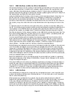
Responses from the instrument to the controller are sent as <
RESPONSE MESSAGES
>, which
consist of one <
RESPONSE MESSAGE UNIT
> followed by a <
RESPONSE MESSAGE TERMINATOR
>,
which is the carriage return character (0DH) followed by the new line character (0AH) with, in
the case of GPIB only, the
END
message NL^
END
. This is shown as <
RMT
> in the descriptions
below.
Each query produces a specific <
RESPONSE MESSAGE
> which is described in the entry for the
query command in the remote commands list below. Most responses consist of a keyword
followed by either text or a number in one of the following formats:
<
NR
1>
An integer without a decimal point or a unit.
<
NR
2>
A fixed point number with a fractional part but no exponent part.
<
NR
3>
A floating point number with both a fractional part and an exponent part.
<
CRD
>
Character Response Data, consisting of the text characters listed.
<
N
>
The number of the output or status register to which the command relates.
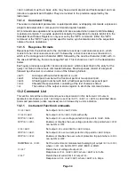
13.2 Command List
This section lists all the commands and queries implemented in this instrument. All numeric
parameters are shown as <
NRF
> and may be sent as <
NR
1>, <
NR
2> or <
NR
3> as described above.
Command parameters (unlike responses) are not followed by a units indication.
13.2.1
Instrument Function Commands
V<
N
> <
NRF
>
Set output <
N
> to <
NRF
> Volts.
V<
N
>V <
NRF
>
Set output <
N
> to <
NRF
> Volts with verify.
OVP<
N
> <
NRF
>
Set output <
N
> over voltage protection trip point to <
NRF
> Volts.
OVP<
N
> <
CPD
>
Enables or disables the over voltage protection trip point where <
CPD
>
can be ON or OFF.
I<
N
> <
NRF
>
Set output <
N
> current limit to <
NRF
> Amps.
OCP<
N
> <
NRF
>
Set output <
N
> over current protection trip point to <
NRF
> Amps.
OCP<
N
> <
CPD
>
Enables or disables the over current protection trip point where <
CPD
>
can be ON or OFF.
DAMPING<
N
> <
CPD
>
Set the current meter measurement averaging of output <
N
> to <
CPD
>,
where <
CPD
> can be ON, OFF, LOW, MED or HIGH.
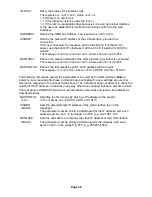
V<
N
>?
Return the set voltage of output <
N
>.
Response is V<
N
> <
NR
2><
RMT
> where <
NR
2> is in Volts.
I<
N
>?
Return the set current limit of output <
N
>.
Response is I<
N
> <
NR
2><
RMT
> where <
NR
2> is in Amps.
Содержание MX180T
Страница 1: ...MX180T MX180TP Triple Output Multi Range DC Power Supply INSTRUCTION MANUAL ...
Страница 44: ......


