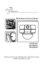


Figure 1 Cover Removal and Replacement
Captive Screws
Cover Assembly
Base Assembly
Alternate Surface Mount
Conduit Connection
Base Gasket
Four Mounting Holes
(#10 or M5 Screws)
7
4.
COVER REMOVAL & REPLACEMENT
1. Using the special Allen wrench provided, remove the 4 tamper resistant
screws located on the cover.The screws are captive and will remain with
the cover. Refer to
Figure 1.
2. Lift the housing off the base to make required camera adjustments. Adjust
the covert liner to position the opening in front of the camera when the
cover is replaced.
3. To replace the cover, align the captive screws with the threaded posts in
the base, fit the cover onto the base and tighten the retaining screws
securely.
5.
INSTALLATION
Attention: Installations should be performed by qualified service
personnel only in accordance with the National Electrical Code or
applicable local codes.
5.1 Connecting Low Voltage Power & Video Signal
(Standard Models)
The wiring harness has a BNC jack to accept video coax.When mounting
directly to a wall or ceiling, run power and video lines to the desired location
using 3/4 inch conduit.
3.
DESCRIPTION & SPECIFICATIONS
These cameras are small, high security surveillance domes containing 1/3-inch
CCD cameras with integral varifocal lenses.The units come ready to use, and
mount easily to a wall or ceiling.
Construction/Finish
: Polycarbonate
Dome on cast aluminum housing.


