background image

Content

Table of Contents

Preface ������������������������������������������������������������������������������������������������� i
Safety Instructions ������������������������������������������������������������������������������ ii
About This Manual ������������������������������������������������������������������������������ iv

Chapter 1� Product Features ��������������������������������������������������������������1

1�1 Box Content ��������������������������������������������������������������������������������������1

1.2 Specifications

 �����������������������������������������������������������������������������������2

1�3 Feature ���������������������������������������������������������������������������������������������2

1.4 8644 with Zoning Configuration and 8644 Port Definition

 ������������������5

Chapter 2� Hardware Setup ����������������������������������������������������������������9

2�1 Top Cover �����������������������������������������������������������������������������������������9
2�2 Power Supply Unit Module ����������������������������������������������������������������9
2�3 Fan Module �������������������������������������������������������������������������������������10
2�4 Disk Drive Module ���������������������������������������������������������������������������11

2.4.1 HDD .................................................................................................................. 11
2.4.2 Drive Slot Map .................................................................................................. 12

2�5 HDD Backplane Module �������������������������������������������������������������������13
2�6 Expander Module ����������������������������������������������������������������������������13
2�7 BMC Module �����������������������������������������������������������������������������������14
2�8 Slide Rail Installation ����������������������������������������������������������������������15

Chapter 3. Sub-system Configuration Setup

 ������������������������������������16

3.1 Supported Configuration and Unsupported Feature

 �������������������������16

3.1.1 Supported Configuration

 ................................................................................. 16

3.1.2 Unsupported Feature ....................................................................................... 16

3�2 Connect Host to JBOD via RS232 ����������������������������������������������������17
3�3 Utility Setup on Host �����������������������������������������������������������������������17
3�4 Updating Firmware and MFG through Console Port �������������������������20

3.5.1 How to enable/disable T10 zoning

 ................................................................. 23

3.5.2 How to configure T10 zoning

 .......................................................................... 24

3.5.3 How to get all revisions in AIC SAS 12G Expander

 ........................................ 26

3.5.4 How to configure temperature sensor(HUB only)

 .......................................... 27

3.5.5 How to configure enclosure address

 .............................................................. 28

3.5.6 How to configure standby timer for all disk drives(EDGE only)

 .................... 29

Содержание JBOD Series

Страница 1: ...UM_J4060 02_v3 1_121619 J4060 02 12Gb s SAS JBOD Series User s Manual...

Страница 2: ...BMC Module 14 2 8 Slide Rail Installation 15 Chapter 3 Sub system Configuration Setup 16 3 1 Supported Configuration and Unsupported Feature 16 3 1 1 Supported Configuration 16 3 1 2 Unsupported Feat...

Страница 3: ...Implementation on SES Pages 40 3 6 4 Implementation on SES Elements 42 3 6 5 SES Element Control Functions 49 Chapter 4 BMC Configuration Settings 56 4 1 Login 56 4 2 Sensor s Location for Fan and Tem...

Страница 4: ...Copyright 2017 AIC Inc All Rights Reserved This document contains proprietary information about AIC products and is not to be disclosed or used except in accordance with applicable agreements...

Страница 5: ...Document Release History Release Date Version Update Content 2017 1 Manual release to public June 2018 3 December 2019 3 1 1 New cover 2 BMC update...

Страница 6: ...le for compliance could void your authority to operate the equipment Disclaimer AIC shall not be liable for technical or editorial errors or omissions contained herein The information provided is prov...

Страница 7: ...y mount the equipment into the rack in such manner that it won t be hazardous due to uneven mechanical loading This equipment is to be installed for operation in an environment with maximum ambient te...

Страница 8: ...ys must not be empty They must have a dummy cover Equipment intended for installed in restricted access location CAUTION Risk of explosion if battery is replaced by an incorrect type Dispose of used b...

Страница 9: ...the hardware is highly advised Do not endanger yourself by placing the device in an unstable environment The consequences for negligent actions may be extremely severe Chapter 3 Sub system Configurati...

Страница 10: ...the carton are damaged If any damage is found do not remove the components contact the dealer where the subsystem was purchased for further instructions Before continuing first unpack the subsystem a...

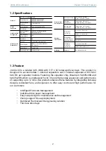
Страница 11: ...eral Number of Expander Single Expander Chip Broadcom SAS35x36R Broadcom SAS35x28R Host Expansion Interface 3 x Mini SAS HD Drives Supported Drive Interface 12Gb and 6Gb SAS SATA Form Factor 3 5 Admin...

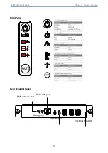
Страница 12: ...Chapter 1 Product Features J4060 02 User Manual 3 Front Panel Rear Expander Panel BMC LAN port BMC console port Debug port Console port 3 x Mini SAS HD...

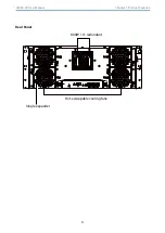
Страница 13: ...Chapter 1 Product Features J4060 02 User Manual 4 Rear Panel 800W 1 1 redundant Hot swappable cooling fans Single expander...

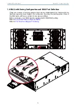
Страница 14: ...ing the zoning option three of the 8644 ports will have a variety of zone group settings Before you begin your JBOD must be equipped with HUB EDGE setting Refer to 3 2 Connect Host to JBOD via RS232 R...

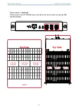
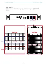
Страница 15: ...60 31 32 33 34 35 36 37 38 39 40 41 42 43 44 45 Left Edge Expander Center Edge Expander Right Edge Expander 16 17 18 19 20 21 22 23 24 25 26 27 28 29 30 1 2 3 4 5 6 7 8 9 10 11 12 13 14 15 Top View To...

Страница 16: ...5 36 37 38 39 40 41 42 43 44 45 Left Edge Expander Center Edge Expander Right Edge Expander 16 17 18 19 20 21 22 23 24 25 26 27 28 29 30 1 2 3 4 5 6 7 8 9 10 11 12 13 14 15 Top View Top View Top View...

Страница 17: ...5 56 57 58 59 60 31 32 33 34 35 36 37 38 39 40 41 42 43 44 45 Left Edge Expander Center Edge Expander Right Edge Expander 16 17 18 19 20 21 22 23 24 25 26 27 28 29 30 1 2 3 4 5 6 7 8 9 10 11 12 13 14...

Страница 18: ...chassis and push the top cover Lift the cover upward to remove 2 1 Top Cover Press the ejector to release the power supply unit Pull the handle to remove the module out of the chassis Push the new po...

Страница 19: ...re Setup J4060 02 User Manual Loosen the thumb screws on the fan module Pull the fan module out of the chassis Align the new fan module with the opening in the enclosure Insert the fan module into cha...

Страница 20: ...tor lever outward Pull the tray from the chassis Insert the hard disk drive into the tray Ensure that the dimples on the tray match the hard disk drive For additional assurance fasten the screws on th...

Страница 21: ...Drive Slot Map The drive slot map follows Left Edge Center Edge Right Edge Left Edge Left Edge Expander Expander Left Edge Expander Center Edge Center Edge Expander Expander Center Edge Expander Right...

Страница 22: ...BOD with LED front board and screw both sides NOTE Before you pull out the HDD backplane please remove all HDD trays and expander modules 2 5 HDD Backplane Module Disconnect all of the cables from the...

Страница 23: ...r Manual Remove the expander module from the chassis Please refer to section 2 4 Place the BMC module on the Expander Module Make sure to match the screw holes Secure the screws Insert the new expande...

Страница 24: ...Sack Slide Rail To install the slide rail please refer to the manual in the slide rail kit Secure the side of th rail with at least one screw NOTE The product installation position is less than 1 met...

Страница 25: ...de ports on each AIC 12G expander controller only the followng drives are supported for shared access 1 SAS drive 2 SATA drive with an interposer which provides SATA to SAS conversion 3 1 2 Unsupporte...

Страница 26: ...es below for DB9 RS 232 cable and SAS expander COM port 3 2 Connect Host to JBOD via RS232 Step 1 Set up host RS232 connection Set up RS232 connection application into your host as shown in the exampl...

Страница 27: ...tion Setup J4060 02 User Manual Step 3 Enter a new name for the icon in the field below and click OK Step 4 Connect by using selecting an option in the drop down menu circled in red below we selected...

Страница 28: ...on Setup Step 6 After step 5 you will enter hyper terminal screen Please press the Enter key and the cmd line will appear on the screen Step 5 Under Bits per second select 38400 Under Flow control sel...

Страница 29: ...Configuration Setup J4060 02 User Manual Step 1 Please input fdl 0 0 in command line to update the firmware Step 2 Select the tool bar Transfer Send File within 10 seconds 3 4 Updating Firmware and M...

Страница 30: ...Chapter 3 Sub system Configuration Setup Step 3 Select the Firmware file and set the Protocol type as Xmodem Then press the Send button Step 4 After completing the FW update Buffer Download Complete...

Страница 31: ...0 in commond line to update the MFG Step 6 Go to the Transfer menu and then select Send file within 10 seconds Step 7 Select the MFG file and set the Protocol type as Xmodem Then press the Send button...

Страница 32: ...system Configuration Setup 3 5 1 How to enable disable T10 zoning The default T10 zoning configuration is off A Check the current zoning state cmd phyzone state Zoning is OFF B Enable zoning cmd phyzo...

Страница 33: ...for the example is A PHY20 PHY23 for the first wide port of HUB B PHY16 PHY19 for the second wide port of HUB C PHY20 PHY21 for drives on EDGE Step 1 Read the current group for PHY16 of HUB cmd phyzon...

Страница 34: ...group for the phy cmd phyzone 19 9 Succeeded to set zone group for the phy cmd cmd cmd cmd cmd _ cmd phyzone 20 8 Succeeded to set zone group for the phy cmd phyzone 21 8 Succeeded to set zone group f...

Страница 35: ...User Manual 3 5 3 How to get all revisions in AIC SAS 12G Expander A Expander firmware revision cmd rev B Expander configuration revision cmd showmfg C MCU firmware revision or sensor information MCU...

Страница 36: ...elsius t1 20 C t2 55 C warning 50 C alarm 55 C B Set temperature with new T1 18 C T2 52 C warning threshold 48 C and alarm threshold 54 C The new setting will take effect after reset cmd temperature 1...

Страница 37: ...500605B0000272BF B Set the enclosure address with 0x500605B0000272BF The new setting will take effect after reset cmd enclosure_addr 500605B0000272BF cmd reset cmd cmd cmd cmd cmd cmd cmd cmd cmd cmd...

Страница 38: ...ives Standby timer is in units of minutes Setting standby timer with 0 minute disables this feature A Get current standby timer cmd standby_timer Standby Timer 0 minutes B Set the standby timer with 1...

Страница 39: ...e power consumption of SAS drives Otherwise AIC Expander Controller starts all attached SAS drives to provide drive access service to any active SAS initiator The same setting should be applied to HUB...

Страница 40: ...31 J4060 02 User Manual Chapter 3 Sub system Configuration Setup...

Страница 41: ...der number 421 12021704510010 or Expander number 421 12021704510010 Enclosure number 526 12071100500088 B Only set Expander serial number with 421 12021704510010 cmd serial_number 421 12021704510010 C...

Страница 42: ...tive SAS initiator by checking all wide ports AIC Expander Controller powers off all attached SAS SATA drives to save power consumption Otherwise AIC Expander Controller powers on all attached SAS SAT...

Страница 43: ...guration Setup J4060 02 User Manual 3 5 10 How to configure EDFB EDGE only The default EDFB configuration is off A Check the current configuration cmd edfb EDFB is OFF B Enable the edfb cmd edfb on C...

Страница 44: ...estoring on AC power loss Three supported options are keep off keep on and keep last state The default setting is keep off A Get the current power setting cmd power_setting Power setting keep off B Se...

Страница 45: ...36 Chapter 3 Sub system Configuration Setup J4060 02 User Manual...

Страница 46: ...ult two zones and three zones The default configuration is one zone of which T10 zoning configuration is disabled T10 zoning configuration of the other configurations two zones and three zones is enab...

Страница 47: ...EDGE Zone 1 Slot 1 60 C 2 When Zone Count 2 T10 zoning is enabled No disk could be seen if we connect HBA RAID card with port 3 of HUB HUB Zone 1 2 Other Wideport 1 2 3 EDGE Zone 1 2 Slot 1 30 31 60 C...

Страница 48: ...t10 org If you are a member of the T10 working group the Standard which controlled by T10 technical committee could be found at http www t10 org cgi bin ac pl t f f ses2r19a pdf 3 6 1 SES pages suppor...

Страница 49: ..._WORD 2 3 PSU Module2 STATUS_WORD 4 5 14 Reserved 0xFF 3 6 3 2 SES Threshold Out In It includes only Temperature Sensor and Voltage Sensor elements Threshold control element format BYTE BIT 7 6 5 4 3...

Страница 50: ...ed N 0 then canister number is restored to default 0x20 0x20 0x20 0x20 0x20 0x20 0x20 0x20 8 spaces in ASCII Canister Number control format BYTE BIT 7 6 5 4 3 2 1 0 0 N Canister Number If no canister...

Страница 51: ...unctions for details B Power Supply Status Element BYTE BIT 7 6 5 4 3 2 1 0 0 COMMON STATUS Reserved PRDFAIL DISABLE SWAP ELEMENT STATUS CODE 1 IDENT Reserved 2 Reserved DC OVER VOLTAGE DC UNDER VOLTA...

Страница 52: ...Element Control Functions for details B Cooling Status Element BYTE BIT 7 6 5 4 3 2 1 0 0 COMMON STATUS Reserved PRDFAIL DISABLE SWAP ELEMENT STATUS CODE 1 IDENT Reserved ACTUAL FAN SPEED MSB 2 ACTUAL...

Страница 53: ...TUS CODE 1 IDENT FAIL Reserved 2 TEMPERATURE 3 Reserved OT FAILURE OT WARNING UT FAILURE UT WARNING Field Value ELEMENT STATUS CODE OK Everything is Ok NON CRITICAL If either warning limit is exceeded...

Страница 54: ...section SES Element Control Functions for details REQUEST WARNING Please refer to section SES Element Control Functions for details B Enclosure Status Element BYTE BIT 7 6 5 4 3 2 1 0 0 COMMON STATUS...

Страница 55: ...Reserved 3 Reserved B Voltage Status Element BYTE BIT 7 6 5 4 3 2 1 0 0 COMMON STATUS Reserved PRDFAIL DISABLE SWAP ELEMENT STATUS CODE 1 IDENT FAIL Reserved WARN OVER WARN UNDER CRIT OVER CRIT UNDER...

Страница 56: ...CONS CHECK Please refer to section SES Element Control Functions for details RQST IN CRIT ARRAY Please refer to section SES Element Control Functions for details RQST IN FAILED ARRAY Please refer to...

Страница 57: ...e Control Element RSVD DEVICE Set by the RQST RSVD DEVICE on Array Device Control Element HOT SPARE Set by the RQST HOT SPARE on Array Device Control Element CONS CHK Set by the RQST CONS CHECK on Arr...

Страница 58: ...command When the RQST IDENT bit is set the blue LED overwrites its default behavior with a slow blink while the red LED is off The blue LED is set Activity for not overwriting its default behavior Th...

Страница 59: ...in the bit4 byte3 of the Array Device Slot control element in the SES specification Set the bit to turn off a slot power and vice versa We use the software package sg3_utils on Linux for example and...

Страница 60: ...SES specification Clear the bit on Power Supply Element DiskPowerSupply to power off all disk drives Set the bit on Power Supply Element DiskPowerSupply to power on all disk drives We use the software...

Страница 61: ...or Power Supply is defined in the bit5 byte3 of the Power Supply control element in the SES specification Clear the bit on Power Supply Element PowerSupply01 or PowerSupply02 to power off the entire e...

Страница 62: ...solid on the identity is enabled The RQST IDENT for Enclosure is defined in the bit7 byte1 of the Enclosure control element in the SES specification Set the bit to enable the identity Clear the bit to...

Страница 63: ...n the bit1 byte3 and bit0 byte3 of the Enclosure control element in the SES specification Setting either bit can enable the enclosure alarm Clearing both bits disables the enclosure alarm We use the s...

Страница 64: ...ESTED SPEED CODE bits Clear RQST IDENT bit to enable the smart fan function again Please disable the smart fan function before changing PWM or fan speed Only Cooling element 0 supports this feature We...

Страница 65: ...a web browser and enter the default IP http 192 168 11 11 When the login window appears set the user name and password to admin Click Log In to continue Type the default account and password Account a...

Страница 66: ...57 J4060 02 User Manual Chapter 4 BMC Configuration Settings EXP EXP T2 T2 T0 T0 Fan2 up Fan0 up Fan3 down Fan1 down FRONT EXP expander chip 4 2 Sensor s Location for Fan and Temperature...

Страница 67: ...Host to BMC by RS232 1 Type the and it will show the IPMI serial interface Type in the command for logging in the interface sys pwd u admin admin It will response OK Type in the command for checking t...

Страница 68: ...30 00 02 01 04 00 00 Find LAN IP 30 00 02 01 03 00 00 Find submask 30 00 02 01 06 00 00 Find gateway 30 00 02 01 0C 00 00 Get LAN static IP DHCP 01 is static IP 02 is DHCP The red box is hexadecimal...

Страница 69: ...00 0A Set submask 30 00 01 01 06 FF FF FF 00 Set gateway 30 00 01 01 0C C0 A8 00 01 The Green returns text that in red box is completion code 00 means OK The blue text can change the value what you w...

Страница 70: ...02 User Manual Chapter 4 BMC Configuration Settings There are have two LEDs under the BMC console Blue LED Light Identify LED Red LED Light When the light keep blinking means BMC got error 4 5 BMC LE...

Страница 71: ...console preview Sensor Monitoring It lists all available sensors on the device with information such as status name reading and status icon as well as a link to that sensor s page There are 3 possible...

Страница 72: ...Chassis information fields Area Format Version Chassis Type Chassis Part Number Chassis Serial Number Chassis Extra Board Information It displays the following Board information fields Area Format Ve...

Страница 73: ...atus using the Power On and Power Off button to control HDD status ACTIONS Power On Select a HDD to turn it power on Power off Select a HDD to turn it power off Icon status Green This slot inserted HD...

Страница 74: ...representation of all associated events Double click on a record to toggle ON OFF the live widget for that particular sensor You can filter the list to view particular sensors only using the drop dow...

Страница 75: ...he device BMC Timezone Check this option to display the event log entries logged with the BMC Timezone value Client Timezone Check this option to display the event log entries logged with the Client u...

Страница 76: ...e hostname of the device Register BMC Choose the BMC s network port to register with the DNS settings Check the option Register BMC to register with the DNS settings Choose the option Direct Dynamic D...

Страница 77: ...and 1 IPv4 DNS server NOTE This is not applicable for manual configuration DNS Server 1 2 3 Specify the DNS Domain Name System server address to be configured for the BMC An IPv4 Address is made of 4...

Страница 78: ...nfiguration settings Obtain an IP address automatically Enable Use DHCP to dynamically configure the IPv4 address using Dynamic Host Configuration Protocol DHCP IPv4 Address Subnet Mask Default Gatewa...

Страница 79: ...y a static IPv6 address to be configured for the selected interface Subnet Prefix length Specify the subnet prefix length for the IPv6 settings Value ranges from 0 to 128 Default Gateway Specify the v...

Страница 80: ...are to be configured Auto Negotiation This option is enabled to allow the device to perform automatic configuration to achieve the best possible mode of operation speed and duplex over a link Link Spe...

Страница 81: ...device Date Specify the current Date for the device Time Specify the current Time for the device NOTE As a year 2038 problem exists the acceptable date range is from 01 01 2005 to 01 18 2038 NTP Serve...

Страница 82: ...ed to display the exact local time NOTE Use the correct UTC Offset after adjusting for DST to automatically synchronize Check this option to automatically synchronize Date and Time with the NTP Server...

Страница 83: ...and available slots You can modify or add new event filter entries here A maximum of 40 slots are available and include the default of 15 event filter configurations Alert Policy Click the Alert polic...

Страница 84: ...t can be enabled under Configuration SMTP Add Select a free slot and click Add to add a new entry to the device Alternatively double click on a free slot Modify Select a configured slot and click Modi...

Страница 85: ...meric characters Space special characters are not allowed Primary SMTP Server It lists the Primary SMTP Server configuration SMTP Support Check this option to enable SMTP support for the BMC Server Ad...

Страница 86: ...ric characters It must start with an alphabet Special characters comma colon semicolon space and backslash are not allowed Password Enter the password for the SMTP User Account Passwords must be at le...

Страница 87: ...02 User Manual 4 6 5 7 Schedule This page displays the device s current date time It can be used to configure dates within a week or specific a date to power on off the device If you want to change t...

Страница 88: ...able schedule Check this option for enable disable the schedule Action Check a action to do power on off for the device Set days for action Setting dates within a week to do power on off for the devic...

Страница 89: ...ified as a security measure To view the page you must have Operator privileges To modify or add a user You must have Administrator privileges NOTE Free slots are denoted by in all columns for the slot...

Страница 90: ...cycle operations Reset Expander Select an expander to do cold reset Power Off Storage Select this option to immediately power off the storage Power On Storage Select this option to power on the stora...

Страница 91: ...6 6 2 JAVA SOL Launch the Java SOL you must have Administrator privileges Choose an expander that can use smart console in Java SOL Volatile Bit Rate Please set 38 4K Non Volatile Bit Rate Please set...

Страница 92: ...Redhat 6 4 NOTE If you want to update a new version firmware for BMC please clear the web browser cookies when the update process is complete 4 7 2 Web update 1 Check if the BMC IP is valid 2 Open a b...

Страница 93: ...84 Chapter 4 BMC Configuration Settings J4060 02 User Manual 3 This is login main page 4 Click the Firmware Update Firmware Update...

Страница 94: ...ation Settings 5 This page will show the update warning If you really want to update the BMC firmware click the Enter Update Mode button 6 Wait few minutes it will pop a window Click the Select file t...

Страница 95: ...ion Settings J4060 02 User Manual 7 Wait a few minutes it will pop a window for checking update section Check the Check this option to do all full firmware flash option 8 Click OK and the firmware wil...

Страница 96: ...update process it will take 3 5 minutes NOTE Please do not close this webpage during the update process to prevent the system from crashing down 10 When Device has been reset window appears it means...

Страница 97: ...Configuration Settings J4060 02 User Manual 1 Click the Firmware Update and it will pop a drop down menu Click the Expand Update 2 Choose the expander firmware file that you want to update 4 8 Expande...

Страница 98: ...89 J4060 02 User Manual Chapter 4 BMC Configuration Settings 3 Choose the expander firmware file and then click the upload button 4 Click the Proceed button...

Страница 99: ...90 Chapter 4 BMC Configuration Settings J4060 02 User Manual 5 Processing 6 Update successful...

Страница 100: ...91 J4060 02 User Manual Chapter 4 BMC Configuration Settings 7 If the update processes is not successful please check the version of the expander firmware whether if the system is turned off...

Страница 101: ...ils or the primary firmware suffers some error it will boot into safety mode 1 If you see the sensor name status LED and ID LED are abnormal the LEDs are cross blinking it means the firmware is in saf...

Страница 102: ...93 J4060 02 User Manual Chapter 4 BMC Configuration Settings...

Страница 103: ...tings J4060 02 User Manual 2 Please clear browser cookies and re start browser The BMC web UI will refresh web page object 3 Click the BMC Reset button to enter the reset page 4 Select the BMC reset a...

Страница 104: ...ge will show Requesting status This web page will be invalid because of resetting the BMC Wait 90 seconds and clear browser cookies to re login to the web UI again 6 If you still see the safety mode p...

Страница 105: ...com tw Support Email support ru aicipc com tw North California United States Address 48531 Warm Springs Boulvard Suite 404 Fremont CA 94539 United States Tel 1 510 573 6730 Fax 1 510 573 6729 Sales Em...

Отзывы: