3. Splice copper wire pigtails to aluminum wire with U.L. recognized connectors for
copper-aluminum splices. Follow these instructions very carefully to make a posi-
tive and lasting connection;
a. Strip insulation from aluminum conductor.
b. Coat the stripped end of the aluminum wire with the recommended inhibitor
and wire brush aluminum surface through inhibitor. Inhibitors: Brundy, Pentex
“A”; Alcoa, No. 2EJC; T&B KPOR Shield.
c. Clean and recoat aluminum conductor with inhibitor.
d. Make the splice using the above listed wire nuts or split bolt connectors.
e. Coat the entire connection with inhibitor and wrap with electrical insulating
tape.
WARRANTY MAY NOT APPLY IF CONNECTIONS ARE NOT MADE PER INSTRUC-
TIONS
C. CONTROL WIRING (Class II)
1. Low voltage wiring should not be run in conduit with power wiring.
2. Control wiring is routed through the 7/8" hole adjacent to the compressor access
panel. Use a minimum #18 AWG thermostat wire. For wire lengths exceeding 50',
use #16 AWG thermostat wire. The low voltage wires are connected to the unit
pigtails which are supplied with the unit in the low voltage connection box located
below the unit control box.
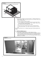
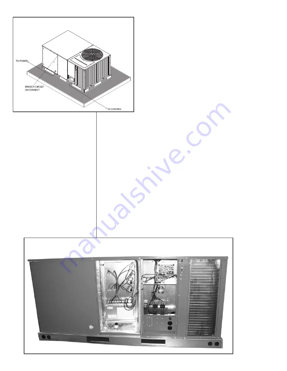
FIGURE 11
HEATER KIT INSTALLATION
FIGURE 10
RECOMMENDED LOCATION OF BRANCH CIRCUIT DISCONNECT
12
Содержание RLNL-C 13 SEER Series
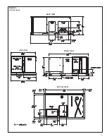
Страница 5: ...5 FIGURE 1 UNIT DIMENSIONS BACK VIEW SIDE VIEW FRONT VIEW BOTTOM VIEW ...
Страница 39: ...39 FIGURE 14 WIRING DIAGRAM ...
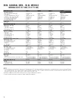
Страница 41: ...3 5 TON AIR CONDITIONER 13 14 SEER 41 ...
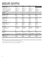
Страница 42: ...4 TON AIR CONDITIONER 13 14 SEER 42 ...
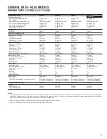
Страница 43: ...5 TON AIR CONDITIONER 13 SEER 43 ...
Страница 46: ...46 ...
Страница 47: ...47 ...
Страница 48: ...48 CM 0610 ...


