C. CLEARANCES
The following minimum clearances must be observed for proper unit performance
and serviceability.
1. Provide 48" minimum clearance at the front of the unit. Provide 36" minimum
clearance at the left and right side of the unit for service access.
2. Provide 60" minimum clearance between top of unit and maximum 3 foot over-
hang.
3. Unit is design certified for application on combustible flooring with 0" minimum
clearance.
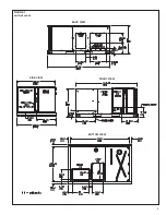
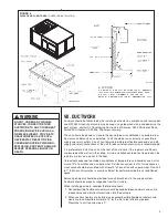
4. See Figure 3 for illustration of minimum installation-service clearances.
D. ROOFTOP INSTALLATION
1. Before locating the unit on the roof, make sure that the strength of the roof and
beams is adequate at that point to support the weight involved. (See specification
sheet for weight of unit.) This is very important and user’s responsibility.
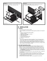
2. For rigging and roofcurb details, see Figures 5 and 6. Use field-furnished spread-
ers.
3. For roofcurb assembly, see Roofcurb Installation Instructions.
4. If the roofcurb is not used, provisions for disposing of condensate water runoff
must be provided.
5. The unit should be placed on a solid and level roofcurb or platform of adequate
strength. See Figure 7.
6. The location of the unit on the roof should be such as to provide proper access for
inspection and servicing.
7. Remove compressor shipping supports (if so equipped) after installation.
IMPORTANT:
If unit will not be put into service immediately, cover supply and return
openings to prevent excessive condensation.
ILL I296
A
B
D
C
38-1/4
CEN
TER
OF
GRA
VITY
25-3
/4
FIGURE 5
PACKAGE AIR CONDITIONER –
RIGGING FOR LIFTING
CORNER WEIGHTS BY PERCENTAGE
A
B
C
D
23%
27%
23%
27%
8
Содержание RLNL-C 13 SEER Series
Страница 5: ...5 FIGURE 1 UNIT DIMENSIONS BACK VIEW SIDE VIEW FRONT VIEW BOTTOM VIEW ...
Страница 39: ...39 FIGURE 14 WIRING DIAGRAM ...
Страница 41: ...3 5 TON AIR CONDITIONER 13 14 SEER 41 ...
Страница 42: ...4 TON AIR CONDITIONER 13 14 SEER 42 ...
Страница 43: ...5 TON AIR CONDITIONER 13 SEER 43 ...
Страница 46: ...46 ...
Страница 47: ...47 ...
Страница 48: ...48 CM 0610 ...


