


NOTE:
1.10 mm orifices provided in kit are used in all alti-
tudes. These orifices comply with the 2% de-rate require-
ments due to the natural de-rate related to lower barometric
pressure.
NOTE
: Use a pipe compound resistant to the action of the liq-
uefied petroleum gases at all threaded pipe connections.
7. Reinstall the manifold assembly by reversing the re-
moval process.
8. Plug the wires into the gas valve.
9. Install the tapped gas nipple supplied with the kit into
the inlet of the gas valve. Be sure to apply pipe dope or
Teflon tape. After tightening the gas nipple, the tapped
hole in the nipple should be in the horizontal position.
See
Figure 35
.
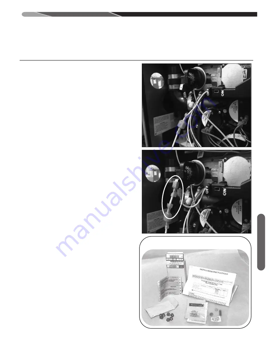
10. Install the Inlet Pressure Switch into the tapped hole. Be
sure to apply pipe dope or Teflon tape. After tightening,
the terminals on the Inlet Pressure Switch should be fac-
ing down towards the blower shelf. See
Figure 36.
11. Remove the connection in the white wire going to the
gas valve. Plug the ¼” female terminal from the gas
valve onto the terminal on the Inlet Pressure Switch.
Using the supplied jumper wire, connect the remaining
¼” male terminal on the white wire to the Inlet Pressure
Switch. See
Figure 37.
12. Reconnect the supply gas line to the furnace.
13. Turn on gas supply and electrical supply.
14. Check unit thoroughly for gas leaks – with soap and water
– not with a flame.
15. Follow lighting instructions to put furnace into operation.
16. Operate thermostat to check unit operation for ignition and
extinction characteristics.
17.
Manifold gas pressure must be adjusted to 10
(
W.C.
after valve conversion to LP gas with furnace in op-
eration and proper gas supply pressure (see rating
plate). The gas supply line pressure should be be-
tween 11
(
and 14
(
W.C. at the appliance.
18.
NOTE:
The igniter wire must not be routed any closer than
1” from the gas valve. Otherwise, noise from the spark ig-
niter wire could reset the valve during ignition trial resulting
in loss of heat.
COMPLETING CONVERSION
1. Using a ballpoint indelible pen, record the following infor-
mation on label 92-18153-05 provided in this kit.
a. Date of conversion.
b. Installer’s name, address and telephone number.
c. Burner orifice size.
2. Place completed conversion label next to the rating plate.
3. Install the burner compartment access door.
LP CONVERSION
49
LP
Co
nv
ers
ion
$$
((
$
$
( (
$
$
$
$
6
( (
$
$
$
$
$
$
$ $
$
$$
$
$
FIGURE 36
$$
((
$
$
( (
$
$
$
$
6
( (
$
$
$
$
$
$
$ $
$
$$
$
$
FIGURE 37
FIGURE 38
TyPICAL LP kIT CONTENTS
Содержание (-)98VA060M317USA
Страница 12: ...Field Conversions FIELD CONVERSIONS 12 ...
Страница 13: ...FIELD CONVERSIONS Field Conversions 13 SEE NExT PAGE FOR APPLICABLE CONFIGURATIONS ...
Страница 15: ...Field Conversions 15 ...
Страница 16: ...Field Conversions ST A1194 68 00 16 ...
Страница 17: ...Field Conversions 17 ...
Страница 18: ...Field Conversions 18 ...
Страница 43: ...43 CONDENSATE DRAIN CONDENSATE DRAIN DRAIN NEUTRALIzER cont Condensate Drain FIGURE 29 ST A1194 70 00 ...
Страница 86: ...86 Timing Diagram TIMING DIAGRAM TABLE 16 TIMING DIAGRAM FOR A CALIBRATION GAS HEAT SEqUENCE ST A1240 03 00 ...
Страница 87: ...87 TIMING DIAGRAM TABLE 17 TIMING DIAGRAM FOR NON CALIBRATION GAS HEAT SEqUENCE Timing Diagram ST A1240 04 00 ...
Страница 92: ...92 Diagnostics TABLE 19 R98V FAULT CODES WITH DESCRIPTIONS AND SOLUTIONS ...
Страница 93: ...93 TABLE 19 continued R98V FAULT CODES WITH DESCRIPTIONS AND SOLUTIONS Diagnostics ...
Страница 94: ...94 Diagnostics TABLE 19 continued R98V FAULT CODES WITH DESCRIPTIONS AND SOLUTIONS ...
Страница 95: ...95 TABLE 19 continued R98V FAULT CODES WITH DESCRIPTIONS AND SOLUTIONS Diagnostics ...
Страница 96: ...96 Diagnostics TABLE 19 continued R98V FAULT CODES WITH DESCRIPTIONS AND SOLUTIONS ...
Страница 97: ...97 TABLE 19 continued R98V FAULT CODES WITH DESCRIPTIONS AND SOLUTIONS Diagnostics ...
Страница 98: ...98 Diagnostics TABLE 19 continued R98V FAULT CODES WITH DESCRIPTIONS AND SOLUTIONS ...
Страница 99: ...99 TABLE 19 continued R98V FAULT CODES WITH DESCRIPTIONS AND SOLUTIONS Diagnostics ...
Страница 100: ...100 Diagnostics TABLE 19 continued R98V FAULT CODES WITH DESCRIPTIONS AND SOLUTIONS ...
Страница 101: ...101 TABLE 19 continued R98V FAULT CODES WITH DESCRIPTIONS AND SOLUTIONS Diagnostics ...
Страница 105: ...105 FIGURE 67 MODULATING ECM FURNACE WIRING DIAGRAM Troubleshooting ...
Страница 106: ...106 ...
Страница 107: ...107 ...
Страница 108: ...108 CM 0717 ...


