


Version October 2015
EN
17
agru EF 110-B User’s Manual
If an inside beadless welding operation with balloon is at hand, manual
data input must also include the pressure inside the balloon (P1) and
the cooling time after the welding process (Tc). This cooling time has
to be observed. If it were cancelled or aborted, the welding system will
reference the joint as a faulty welding operation.
4.5.2 Entering the String of Numbers
If this option was chosen in the manual parameter input menu, the “Enter
Fitting Code” display shows. The 24 or 34 characters of the electrofu-
sion fitting code to be entered display as plus characters ( + ). Use the
alphanumeric keypad (see last Info in Sect. 4.1) to enter the code and
press START/SET to confirm your input and have it decoded. If the code
entered is not correct, a “Code Error” message appears; check the string
of numbers and correct as needed. If the code is correct, the decoded
data is displayed, and the “Start ?” message (see Display 10) indicates
that the unit is ready to start welding.
Inside beadless welding with inside balloon is possible only when a
34-character code is entered, since a 24-character code does not in-
clude any data on controlling balloon pressure and cooling time. If a
24-character code is entered, the system starts a welding process with
balloon control.
Important
Only when the manual welding parameter input includes either
a balloon pressure (P1) of more than 0 bar or a 34-character
fitting code, inside beadless welding with balloon control is
possible. If it does not, the balloon control subsystem is not
even started when the welding process begins.
Info
If a cooling time (Tc) is entered in the manual parameters, this
cooling time has to be waited before the cable between the
system and the electrofusion fitting is disconnected. If a cool-
ing time was entered and yet the cooling stage was cancelled,
the system will assess the joint as being faulty.
4.6 Performing the Welding Process
4.6.1 Facing the Component Ends before Welding
If the diameter of the components to be jointed is smaller than the maxi-
mum size of the clamps, install the appropriate reducers in the clamps.
This does not require any tools. Magnets hold the reducer inserts
in the clamps.
Unlock all three carriages (left-hand and right-hand clamp and
facing tool/fitting clamp carriage) at their respective star knobs.
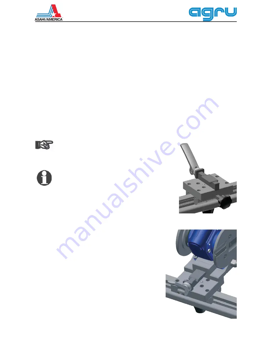
Then slide the power facing tool as far as it will go onto the seat
on top of the carriage of the mechanical structure and lock it in
place by pushing the quick release lever down.
Insert the components to be jointed into the clamps, one of them
left, the other, right of the facing tool. Be sure that on both sides
they project enough over the clamps on the inside for the blade
of the facing tool to be able to cut a sufficient length of material
while facing. The spacer pins on both sides of the facing tool will
facilitate this process: when the component butts touch the the
facing tool, the spacer pins must not touch yet the inside surface
of the clamps.
Reposition the outer clamps on both sides as needed by loosening
then retightening the thumb screw at their far end.
Star knob locking the fitting
clamp/facing tool carriage
(identical knob on the other carriages)
Sliding the facing tool onto the seat on
top of its carriage; to lock, lower quick
release lever on the front of the seat


